Basic Civil & Mechanical Engineering: UNIT IV: d. Hydraulic Turbines
Reaction Turbines
Francis and Kaplan Hydraulic Turbine - Diagram, Working Principle, Construction
If, at the inlet of the turbine, the water possesses both kinetic energy as well as potential energy, the turbine is known as Reaction Turbine.
REACTION TURBINES
Principle
If, at the inlet of the turbine, the water
possesses both kinetic energy as well as potential energy, the turbine is known
as Reaction Turbine. It requires low / medium head with high rate of flow. All
the pressure energy of water is not completely converted into kinetic energy,
as in the case of the impulse turbine.
First,
water enters the guide blades, which guide the water to enter the moving
blades. In the moving blades, part of the pressure energy is converted into
kinetic energy, which causes rotation of the runner. Water leaving the moving
blades is at a low pressure.
Thus,
there is a pressure difference between the entrance and the exit of the moving
blades. This difference in pressure is called Reaction. Pressure acts on moving
blades and causes the rotation of the wheel in the opposite direction.
1. FRANCIS TURBINE
Francis
Turbine was developed by the American Engineer Francis in 1850. It is an inward
flow radial type reaction turbine. It operates under medium head.
Working Principle [Fig. 2]
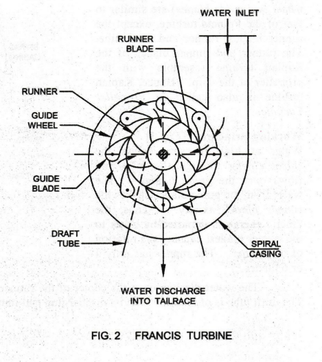
Francis turbine consists of a Spiral Casing,
Fixed Guide Blades, Runner, Moving Blades and Draft Tube.
The
spiral casing encloses a number of stationary guide blades. The guide blades
are fixed around the circumference of an inner ring of moving blades. Moving
blades are fixed to the runner.
Water
at high pressure from the penstock pipe enters the inlet in the spiral casing.
It flows radially inwards to the outer periphery of the runner through the
guide blades. From the outer periphery of the runner, water flows inwards
through the moving blades and discharges at the center of the runner at a low
pressure. During its flow over the moving blades, water imparts kinetic energy
to the runner, causing the rotation of the runner.
Draft
tube is a diverging conical tube fitted at the center of the runner. It enables
the discharge of water at low pressure. The other end of the draft tube is
immersed in the discharging side of the water, called tail race.
2. KAPLAN TURBINE
Kaplan
Turbine is a low head reaction turbine, in which water flows axially. It was
developed by German Engineer Kaplan in 1916.
All the parts of the Kaplan turbine (viz.,
spiral casing, guide wheel and guide blades) are similar to that of the Francis
turbine, except the runner blades, runner and draft tube. The runner and runner
blades of the Kaplan turbine resemble with the propeller of the ship. Hence,
Kaplan turbine is also called as Propeller Turbine.
Working
Principle [Fig. 3]
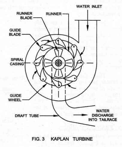
Water
at high pressure enters the spiral casing through the inlet and flows over the
guide blades. The water from the guide blades strikes the runner blades
axially. Thus, the kinetic energy is imparted by water to the runner blades,
causing the rotation of the runner. The runner has only 4 or 6 blades.
The
water discharges at the center of the runner in the axial direction into the
draft tube. The draft tube is of L-shape with its discharging end immersed into
the tail race.
Basic Civil & Mechanical Engineering: UNIT IV: d. Hydraulic Turbines : Tag: : Francis and Kaplan Hydraulic Turbine - Diagram, Working Principle, Construction - Reaction Turbines
Related Topics
Related Subjects

Basic Civil and Mechanical Engineering
BE3255 2nd Semester 2021 Regulation | 2nd Semester EEE Dept 2021 Regulation