Electrical Machines: Unit II: D.C. Generators
Reduction of Effects of Armature Reaction
DC Generators
In order to reduce the effect of armature reaction following methods are used.
Reduction
of Effects of Armature Reaction
AU: Dec.-05, 09
In
order to reduce the effect of armature reaction following methods are used.
1.
The armature reaction causes the distortion in main field flux. This can be
reduced if the reluctance of the path of the cross-magnetising field is
increased. The armature teeth and air gap at pole tips offer reluctance to
armature flux. Thus by increasing length of air gap, the armature reaction
effect is reduced.
2.
If reluctance at pole tips is increased it will reduce distorting effect of
armature reaction. By using special construction in which leading and trailing
pole tip portions of laminations are alternately omitted.
3.
The effect of armature reaction can be neutralized by use of compensating
winding. It is always placed in series with armature winding. The armature
ampere conductors under pole shoe must be equal to compensating winding ampere
conductors which will compensate armature m.m.f. perfectly.
4.
The armature reaction causes shifting the magnetic neutral axis. Therefore
there will be some flux density at brush axis which produces e.m.f. in the coil
undergoing commutation. This will lead to delayed commutation. Thus the
armature reaction at brush axis must be neutralised. This requires another
equal and opposite m.m.f. to that of armature m.m.f. This can be applied by
interpoles which are placed at geometric neutral axis at midway between the
main poles.
•
Out of the different methods mentioned above, used to reduce the effects of
armature reaction, let us see the method of providing compensating winding in
detail. This method is very popularly used in actual practice for d.c.
machines.
1. Use of Compensating Winding
•
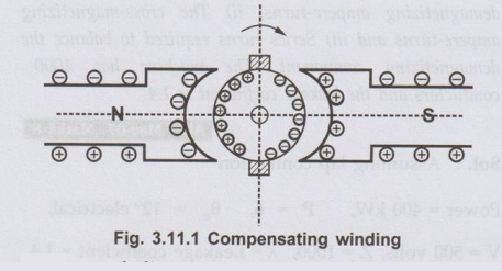
The compensating windings are basically used to neutralise the armature flux in
the pole arc region which will otherwise cause severe distortion of main field
flux. These windings are of concentric type and
are placed in axial slots in the pole faced as shown in the Fig. 3.11.1
•
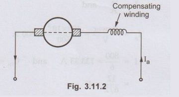
The symbolic representation of compensating winding is shown in the Fig.3.11.2.
•
The armature reaction causes the displacement of main field flux. It affects
the waveform of main field flux and makes it non-uniform. The effect of
armature reaction depends upon armature current which inturn depends on the
load on the machine.
• In case of machines having large
fluctuations in load such as rolling mill motors or turbogenerators, the
armature reaction will cause sudden shift of flux in backward and forward
direction depending on change in the load. This will cause statically induced
e.m.f. in the armature coils whose magnitude depends upon how fast the load is
changing and by what amount it is changing. There is dynamically induced e.m.f.
in the armature coil also. Under worst conditions these two e.m.f.s may become
additive. This will occur when load is increased on motor and decreased from
generator. If this e.m.f. is more than the breakdown voltage across adjacent
commutator segments, a sparkover may occur which can easily spread over as
conditions near commutator are favourable for flashover. The maximum allowable
voltage between the segment is 30 to 40 V. Thus there is always danger of short
circuiting the whole armature if armature flux is not compensated.
•
This can be achieved by the use of compensating winding which will neutralize
the effect of armature reaction. These windings are connected in series with
the armature. The current in these windings flows in opposite direction to that
in armature conductors below the pole shoes. This will counterbalance the cross
magnetising effect of armature reaction which may cause flashover between the
segments.
Key Point:
To have perfect neutralization of armature m.m.f. under the pole shoe, the
ampere conductors of compensating winding must be equal to total armature
ampere conductors under the pole shoe.
Ampere
turns per pole for compensating winding
=
Pole arc / Pole pitch × Armature ampere turns per pole
Total
ampere conductors per pole = Ia / A Z / P
Since
two conductors form one turn.
Total
ampere turns per pole in armature = ½ .
Ia /A Z/P
ஃ
Ampere turns per pole for compensating
Winding
= Ia . Z / 2A P × Pole arc / Pole pitch
•
Since the distribution of armature m.m.f. and compensating winding m.m.f. is
not identical the complete neutralization of armature m.m.f. can not be
achieved by using compensating winding. The armature m.m.f. under the pole shoe
is neutralized whereas there is incomplete neutralization in the interpolar
region. There will be small flux density remaining unneutralized in GNA. This
can be neutralized by using interpole windings.
•
Thus by using interpole as well as compensating windings, the armature reaction
effect is completely neutralized over the entire armature periphery. The only
flux present in the machine will be main field flux which will be an ideal
situation.
•
Though compensating windings are very expensive they are provided in machines
which carry heavy overloads or there is rapid change in the load. So that there
will not be any possibility of flashover.
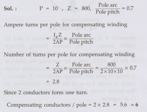
Ex. 3.11.1
Calculate the number of conductors on
each pole piece in a compensating winding for a 10 pole d.c. generator which
has lap wound armature containing 800 conductors. Assume ratio of pole arc to
pole pitch to be 0.7.
Sol. :
Review Question
1. Briefly explain
the methods to overcome the adverse effects of the armature reaction. AU: Dec.-05, 09,
Marks 12
Electrical Machines: Unit II: D.C. Generators : Tag: : DC Generators - Reduction of Effects of Armature Reaction
Related Topics
Related Subjects

Electrical Machines I
EE3303 EM 1 3rd Semester EEE Dept | 2021 Regulation | 3rd Semester EEE Dept 2021 Regulation