Electromagnetic Theory: Unit V: Electromagnetic Waves
Reflection of Uniform Plane Waves
Electromagnetic Waves
• We have, so far, studied the uniform plane waves travelling in unbounded and homogeneous media. But practically, very often, waves propagate in bounded regions consisting several media of different constitutive parameters such as Ɛ, µ, σ, ɳ etc.
Reflection of Uniform Plane Waves
AU
: Dec.-05,06,14,16,17,19, May-08,15,16,17
• We have, so far, studied the uniform plane waves travelling in unbounded and homogeneous media. But practically, very often, waves propagate in bounded regions consisting several media of different constitutive parameters such as Ɛ, µ, σ, ɳ etc. Before we actually start with the reflection of the uniform plane wave, let us consider simple example of a transmission line.
•
Consider a transmission line having a characteristic impedance Z0.
Assume that a line is terminated in load impedance ZL .
If
the load impedance ZL equals the characteristic impedance Z0
(i.e. ZL = Z0), then the line is said to be properly
terminated.
•
If ZL ≠ Z0, then there is a mismatch between the two
impedances and the line is not properly terminated. Consider that the wave
travelling along the line incidents at the load. The part of the wave gets
absorbed by the load ; while other part is reflected back to the generator. So
we can say reflection occurs at the load if ZL ≠ Z0. If
there are two waves ; one incident in forward direction, while other reflected
back in backward direction, then the standing waves are said to be produced
along the line.
•
Now consider again the uniform plane wave travelling in non-homogeneous media.
When a uniform plane wave travels from one medium to other having different
intrinsic impedances, the reflection takes place at the boundary. The part of
the wave is transmitted in medium 2 and remaining part is reflected back to
medium 1, depending upon the constitutive parameters of media. Depending upon
the manner in which the uniform plane is incident on the boundary, there are
two cases of incidence.
i)
Normal incidence : When a uniform plane wave incidences
normally to the boundary between the media, then it is known as normal
incidence.
ii)
Oblique incidence : When a uniform plane wave incidences
obliquely to the boundary between the two media, then it is known as oblique
incidence.
In
this section we shall focus on the interface between,

i)
Two dielectric media and
ii)
Dielectric and conductive media.
1. Normal Incidence at Plane Dielectric Boundary
•
Consider a uniform plane wave striking the interface between the two
dielectrics at right angles as shown in the Fig. 10.10.1.
•
Assume that a uniform plane wave travels along +z direction and incidence at
right angles at the boundary between two dielectric media i.e. at z = 0. Below
z = 0, let the properties of medium 1 be Ɛ1, µ1, σ1,
ɳ1 and above z = 0, the properties of medium 2 be Ɛ2, µ2,
σ2, ɳ2. So depending upon the properties of two media,
part of the wave will be transmitted in medium 2 while other part will be
reflected back in medium 1.
•
Let Ei and Hi be the field strengths of the incident wave
striking the boundary. Let Et and Ht be the field
strengths of the transmitted wave in the medium 2. And let E and Hr be
the field strengths of the reflected wave in the medium 1 returning back from
the interface.
•
From the Fig. 10.10.1 it is clear that in medium 1, the total field comprises
both the incident and reflected fields. But in medium 2, only the transmitted
field gives the total field. So the conditions for the total fields in medium 1
are given by,

•
Similarly the conditions for the total fields in medium 2 are given by,

•
According to the boundary conditions, the tangential components of ![]() and
and ![]() must
be continuous at the interface z = 0. As we know the waves are transverse in
nature, at the boundary we get both the fields
must
be continuous at the interface z = 0. As we know the waves are transverse in
nature, at the boundary we get both the fields ![]() and
and ![]() both tangential to
the interface.
both tangential to
the interface.

•
Thus at the interface z = 0, we can write

•
The relationships between the magnitudes of ![]() and
and ![]() at z = 0 are given
by following expressions.
at z = 0 are given
by following expressions.
Ei
= η1 Hi,
Er
= - η1 Hr
....
As direction of reflected wave is opposite to that of incident wave
Et
= η2 Ht
Interms
of magnitudes of the fields ![]() and
and ![]() at the interface, we can write,
at the interface, we can write,
Ei
+ Er = Et ... (10.10.1)
and Hi + Hr = Ht ... (10.10.2)
•
In equation (10.10.2), putting values of Hi, Hr and Ht
interms of E, Er and Et respectively,

•
Adding equations (10.10.1) and (10.10.3),

•
The transmission coefficient is denoted by r and it is given by,
τ
= Et / Ei = 2 η2 / η1 + η2
•
Eliminating Et from equations (10.10.1) and (10.10.3), we get,

•
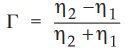
The reflection coefficient is denoted by T and it is given by,
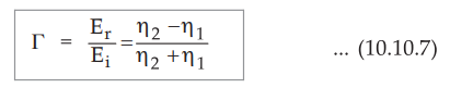
•
From equations (10.10.5) and (10.10.7), we can draw some important results as,
a)
1 + ɼ = τ
b) 0 ≤ | ɼ | ≤ 1
c)
Both the coefficients ; ɼ and τ are dimensionless and may be complex in nature.
•
According to Poynting theorem, the average power density is given by,
Pavg
= 1/2 E2m/ɳ W/m2
•
Where Em is the amplitude of the electric field intensity and η is
the intrinsic impedance of a medium.
•
The average power transmitted in medium 1 is given by,

•
The average power reflected in medium 1 is given by,

•
Similarly the average power transmitted in medium 2 is given by,

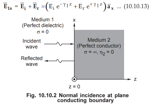
2. Normal Incidence at Plane Conducting Boundary
•
Consider a uniform plane wave striking the interface between two media ; where
medium 1 is perfect dielectric (σ = 0, lossless) and medium 2 is perfect
conductor (σ = ∞). For medium 2, intrinsic impedance ɳ2 = 0 being a perfect
conductor. Thus the transmission coefficient is given by,
τ
= 2η2 / η1 + η2 = 0 … (10.10.11)
•
Also the reflection coefficient is given by,
τ
= 2η2 – η1 / η2 + η1 = -1 …
(10.10.12)
• From the values of the reflection and transmission coefficients it is clear that the wave is totally reflected and there is no transmitted wave in medium 2. It is obvious from the fact that no field can exists in the perfect conductor. As totally reflected wave combines with the incident wave, standing waves are formed.
•
A standing wave does not travel and it consists of two travelling waves; one
incident (![]() ) and other reflected (
) and other reflected (![]() ). Both the waves have same
amplitudes but the directions in which they propagate are different.
). Both the waves have same
amplitudes but the directions in which they propagate are different.
•
Let the standing wave in medium be
denoted by ![]() . Thus in phasor form we can write,
. Thus in phasor form we can write,
But
as the reflection coefficient is
ɼ
= Er / Ei = -1
•
Also for medium 1, σ = 0 indicates perfect dielectric medium.

• Exactly similar to above derivation, we
can obtain magnetic field ![]() in medium 1 as
in medium 1 as

• From equations (10.10.17) and (10.10.18) it is clear that the total fields in the medium 1 are not travelling eventhough these fields are obtained by adding two waves of equal amplitude but travelling in opposite directions. Also in these two equations, the factors with time and distance are represented by separate trigonometric terms.
•
Consider the equation for total electric field in medium 1 given by equation
(10.10.17). This field is zero everywhere whenever ωt = n π . Also this field
is zero for all time at the planes for which β1 z = n π.
•
The planes at which the electric field is zero are located where,

•
The above condition clearly indicates that the electric field is zero at z = 0
and it repeats after every half wavelength from the boundary in the medium 1
where z < 0. The Fig. 10.10.3 shows the instantaneous values of the electric
field in medium 1 at t = π/2

• Now consider equation (10.10.18)
representing a standing wave. The magnitude of the magnetic field is maximum at
the positions where the electric field is zero. Furthermore it is 90° out of
time phase with the electric field everywhere.
a.
Standing Wave Ratio (SWR)
•
In the last section we have studied that the electric field is zero at boundary
and repeats at every half wavelength distance from boundary in medium 1 (z <
0). At the same time, the magnitude of the magnetic field is maximum at the
positions where the electric field is zero. By using a simple probe, relative
amplitudes of electric or magnetic field intensity are easily measured. By
using a small coupling loop, amplitude of the magnetic field can be measured.
While by using a simple co-axial cable, amplitude of the electric field can be
measured. To measure actual indication, the output of the probe is connected to
either microammeter, millivoltmeter or any special display device.
•
Consider a uniform plane wave travelling in a lossless medium with no reflected
wave present in the medium. It is observed that the relative amplitude of the
field is same at every point. It is obvious that the instantaneous field
undergoes phase change of β (z2 -z1) when the probe is moved from z = z1 to z =
z2 along a wave. Thus we can conclude that unattenuated travelling wave shows
equal amplitude voltages characteristic.
•
Now consider a uniform plane wave travelling in a lossless medium ; it gets
reflected back by the perfect conductor. This results in the generation of
standing wave. When the voltage probe is located at the interface i.e. z = 0
and at every integral number of half wavelengths from the interface in medium 1
(z < 0) ; the output of the probe will be zero. When the position of probe
is changed, the amplitude of the field varies as |sinβ z| as shown in the Fig.
10.10.4.
•
Note that z is the distance from the interface.
•
The total field in medium 1 is obtained by adding incident and reflected field
intensities. Thus the total field in medium 1 along standing wave is given by,

•
Let the medium 1 be perfect dielectric. So σ = 0 and ɑ = 0. Thus the
propagation constant is ɤ = jβ Also the reflection coefficient is given by,

•
Then the total field in medium 1 is given by,

•
The reflection coefficient can be expressed interms of intrinsic impedances of
the two media as,
•
As we have already studied that, r may be complex ; so we can write the
reflection coefficient in phasor form as,

•
Here depending upon the nature and values of η1 and η2 we get three conditions for an angle
ϕ
i)
If medium 2 is perfect conductor, ϕ = π
ii)
If η2 is real and η2 < η1 ; ϕ = π
iii)
If η2 is real and η2 < η1 ; ϕ = 0
•
Then the total field in the region is given by,

•
Let us check out the conditions for the maximum and minimum values of the
magnitude.
•
It is obvious that when the incident and reflected waves are in phase, we get
maximum amplitude of the field. That means the phase angle of both the waves is
same.

•
And this maxima occurs where,

•
Consider that η1 and η2 both are real and η2 and
η1 . Then we get voltage maximum at interface (i.e. z = 0) if ϕ = 0.
•
If the interface is between a perfect dielectric and a perfect conductor, then ϕ
= π Then the voltage maximum occurs at
-
β1z = π/2, 3π/2 and so on
•
When incident wave and reflected wave are out of phase by 180°, we get minimum
voltage.

And
this minima occurs where
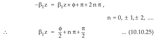
•
From the equation (10.10.25) it is clear that the voltage minima are separated
by λ /2 distance. Thus voltage minima occurs at - β1z = 0 for perfect
conductor.
•
In general voltage minima are separated by one half wavelength. Also the
voltage maxima are also separated by one half wavelength.
•
The standing wave ratio (S) is defined as the ratio of maximum to minimum
amplitudes of voltage.

•
When the amplitudes of reflected and incident waves are equal, | ɼ | = 1. Thus s is infinite indicating total
energy is reflected.
•
When there is no reflection of energy i.e. η2 = η1
then ɼ = 0. Thus s is unity.
•
The standing wave ratio s is dimensionless and the value of s lies in the range
1
≤ s ≤ ∞.
•
We can express reflection coefficient (r) interms of the standing wave ratio
as,
|ɼ|
= S – 1 / S + 1 ...(10.10.27)
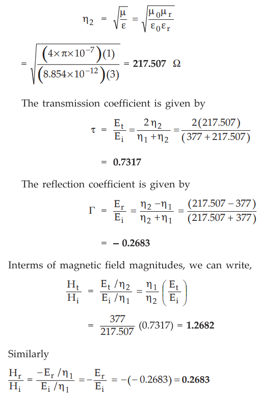
Ex.
10.10.1 ![]() and
and ![]() waves, travelling in free space, are normally incident on
the interface with a perfect dielectric with Ɛr =3. Compute the magnitudes of
incident, reflected and transmitted
waves, travelling in free space, are normally incident on
the interface with a perfect dielectric with Ɛr =3. Compute the magnitudes of
incident, reflected and transmitted ![]() and
and ![]() waves at the interface.
waves at the interface.
Sol.
: For
medium 1, i.e. free space,
η1
= 120π = 377 Ω
For
medium 2, i.e. perfect dielectric,
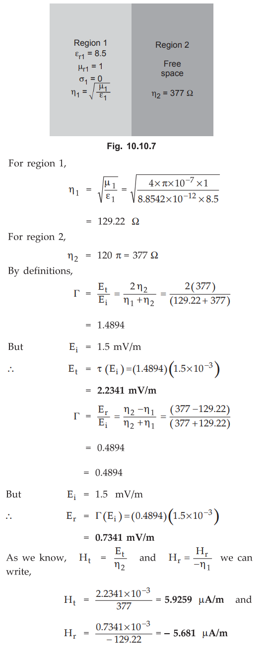
Ex.
10.10.2 Determine the amplitudes of reflected and transmitted fields (electric
and magnetic both) at the interface of two regions, if Ei = 1.5 mV/m in region
1 for which Ɛr1 = 8.5, µr = 2 and σ = 0
and region 2 is a free space.
AU
: Dec.-05, Marks 8
Sol.
:
The interface is between perfect dielectric (region 1) and free space (region
2).

Ex. 10.10.3 A free space-silver interface has E (incident) = 100 Vhn on the free space side. The frequency is 15 MHz and the solve constants are Ɛr = µr =1 σ = 617 MS/m Determine E (reflected), E (transmitted) at the interface.
AU
: Dec.-06, May-17, Marks 8
Sol.
:
The conductivity of silver is given as a = 61.7 MS/m >> 1, it can be
considered as good conductor.

Thus
the intrinsic impedance for good conductor is given by,

Key
Point : Note that 180° angle represents that the wave
propagates in opposite direction to that of the incident wave. Er is
almost equal to Ei indicates that the wave cannot propagate in good conductor
but gets totally reflected.
Ex.
10.10.4 Determine the amplitude of the reflected and transmitted E and H at the
interface of two media with the following properties. Medium 1 :t:.Ɛr = 8.5,µr
=1 σ = 0 Medium 2; free space. Assume normal incidence and the amplitude of E
in the medium 1 at the interface is 1.5 mV/m.
AU
: Dec.-05, Marks 8
Sol.
:
The interface is between perfect dielectric (region 1) and free space (region
2).
Ex.
10.10.5 A plane wave travelling in +z direction in free space (z < 0) is
normally incident at z = 0 on a conductor (z > 0) for which σ = 61.7 MS/m, µr
= 1. The free space E wave has a frequency f = 1.5 MHz and an amplitude of 1.0
V/m at the interface it is given by  Analyse the wave and predict
magnetic wave
Analyse the wave and predict
magnetic wave ![]() (0, t) at z > 0.
(0, t) at z > 0.
Sol.
:
For
z > 0, in complex form,

Ex.
10.10.6 A plane wave travelling in air is normally incident on a block of
paraffin with Ɛr = 2.2. Find the reflection coefficient.
AU
: May-15, Marks 4
Sol.
:
Medium 1 : Air i.e. free space.
Hence
η1 = η2 = 377 Ω
Medium
2 :
Paraffin with Ɛr = 2.2, µr = 1.

Examples
for Practice
Ex.
10.10.7 In free space (Z ≤ 0) a plane wave with  is incident normally on a lossless medium (Ɛ = 2 Ɛo, µ = 8µo) in region Z ≥ 0.
Determine reflected wave
is incident normally on a lossless medium (Ɛ = 2 Ɛo, µ = 8µo) in region Z ≥ 0.
Determine reflected wave 
[Ans.:
6.669 × 10⁻³ A/m, - 3.33 × 10⁻³ A/m, - 5025.41 cos (108t-β2z) ![]() mV/m ]
mV/m ]
Ex.
10.10.8 A travelling ![]() field in the free space of amplitude 100 V/m,
strikes a perfect dielectric, as shown in the Fig. 10.10.8. Determine
Et.
field in the free space of amplitude 100 V/m,
strikes a perfect dielectric, as shown in the Fig. 10.10.8. Determine
Et.
[Ans.:
59.7125 V/m]
Review Questions
1. Explain reflection
of uniform plane waves with normal incidence at a plane dielectric boundary.
AU: May-16, Dec.-19,
Marks 10
2. Obtain solution for
a uniform plane wave in an isotropic homogeneous dielectric medium.
3. Derive the transmission
and reflection coefficients for the electromagnetic waves.
AU May-08, Marks 8
4. Derive the
transmission and reflection coefficients at the interface of two media for
normal incidence.
AU: Dec.-06, Marks 8
5. Briefly explain
about wave incident normally on perfect conductor.
AU: Dec.-14, Marks 8
6. Write a note on
standing wave ratio.
AU: Dec.-14, 17, May-16, Marks 6
Electromagnetic Theory: Unit V: Electromagnetic Waves : Tag: : Electromagnetic Waves - Reflection of Uniform Plane Waves
Related Topics
Related Subjects

Electromagnetic Theory
EE3301 3rd Semester EEE Dept | 2021 Regulation | 3rd Semester EEE Dept 2021 Regulation