Electrical Machines II: UNIT V: b. Special Machines
Repulsion Motors
Construction, Working Principle, Characteristics
Repulsion motors work on the principle of repulsion between two magnetic fields. These motors give excellent performance characteristics.
Repulsion Motors
Repulsion
motors work on the principle of repulsion between two magnetic fields. These
motors give excellent performance characteristics. Before going to actual
discussion about motor let us consider the principle on which motor works.
1. Repulsion Principle
For
understanding the torque production by motor using repulsion principle consider
a two pole salient pole motor having magnetic axis horizontal. The armature of
the machine consists of a d.c. windings having commutator and brushes. The
brushes are short circuited by a low resistance jumper.
The
stator winding is given excitation in such a way as to form the poles as shown
in the Fig. 9.5.1.
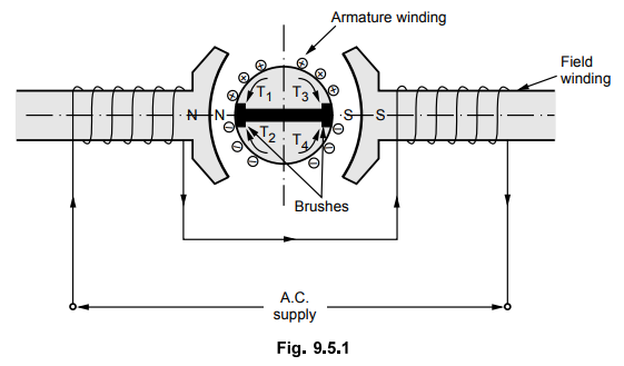
The
brushes are aligned in the same direction of the field axis. The stator winding
will produce alternating flux which will induce emf in the armature conductors
by transformer action. The direction of induced emf can be found by using
Lenz's law. The direction of induced current will depend on position of
brushes. These currents will lag behind the induced voltages by almost 90°.
Because of the current flowing through the armature, it will produce its own
magnetic field with the poles as shown in Fig. 9.5.1. Thus equal force of
repulsion exists between like poles which will not produce any torque.
Alternatively it can also be explained as the armature to be divided into four
quadrants producing four torques T1,T2,3 and T4 which are
equal and hence the net torque is zero.
If
brushes are shifted by 90o, so the conductors undergoing short circuit are also
changed. The induced emf are in the same direction as before. The arrangement
is shown in the Fig. 9.5.2
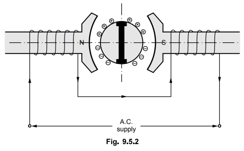
Apart
from the coils undergoing short circuit, the remaining armature winding gets
divided into two parallel paths. It can be seen that the induced emfs are
balanced and the resultant emf is zero. Thus no current flows through the
brushes and the resultant torque is also zero.
Now
if the brushes are in the position shown in the Fig. 9.5.3.
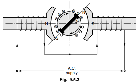
In
this case, the brushes axis is not in the line of main field or at an angle of
90° to main field but it is at an angle of a with the main field.
Again
the emf will be induced in the armature conductors and there will be net
voltage across brush terminals which will produce current in the armature. Thus
the armature will also produce its own magnetic field with the poles as shown
in the Fig. 9.5.3. The north and south poles of stator and rotor will attract
each other and there will be net torque available which will run the motor in
the clockwise direction. Alternatively we can say that the north pole formed by
armature winding will be repelled by the north pole formed by the main field
winding and similarly the south pole will be repelled by south pole formed by
the main field winding and the motor runs in clockwise direction. As the forces
are of repulsion which contributes in the motion so the name of the motor is
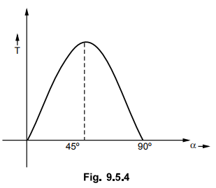
repulsion motor. If the brush is given shift in the opposite direction to that
shown in the Fig. 9.5.4 then motor rims in anticlockwise direction which can
also be explained on the similar lines. Hence the position of brushes decides
the direction of rotation. The torque produced by the motor depends on the
brush shift angle ɑ.
Key Point For a = 45 °
maximum torque is available.
Thus
the control of speed and torque can be done with the help of brush shift. The
variation of torque with brush shift is shown in the Fig. 9.5.4.
2. Repulsion Type Motors
The
motors which use the principle as explained in the earlier section are called
repulsion type motors which are categorised into four distinct groups which are
as given below.
1)
Repulsion motor
2)
Compensated repulsion motor
3)
Repulsion start induction rim motor
4)
Repulsion induction motor.
1)
Repulsion motor
The
principle of operation of this motor is already explained in earlier section.
This motor consists of a stator and rotor winding alongwith commutator and a
set of brushes. The rotor winding is same as d.c. winding whereas brushes are
short circuited having contact with commutator at all times. Normally there are
four, six or eight poles on the stator.
The
stator winding is of distributed non-salient pole type mounted in the slots. A
rotor is also having slots for distributed winding. The winding on rotor is
connected to the commutator which may be either axial or radial. The brushes
are made up of carbon fitted in brush hold which press on the commutator and
carries the current in the rotor winding.
With
this type of motor, a very high starting torque (of about 300 to 350 % of full
load) can be obtained with starting current of about 3 to 4 times the full load
current. Thus it has got very good operating characteristics but the motors are
expensive and rarely used in the applications. Also the speed of the motor
changes with load. At no load its value is very high. There is possibility of
sparking at brushes and the motor runs at low power factor.
2.
Compensated Repulsion Motor
It
is the modified form of the repulsion motor. It is often required that the
motor should run at constant speed and with higher power factor. These
conditions can be met by the use of additional inner stator winding which is
smaller than the outer commutator winding. The torques developed are thus
additive. This additional winding is called compensating winding. It is
connected in series with the rotor winding. It consists of additional set of
brushes placed in the mid way between the normal short circuited brushes as
shown in the Fig. 9.5.5.
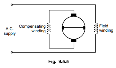
The
machine with this modification runs with improved power factor as the
quadrature drop in the field winding is neutralised or compensated with this
additional winding. Also the leakage between armature and field is reduced. It
gives better speed regulation.
3.
Repulsion Start Induction Run Motor
In
order to obtain constant speed and high starting torque, repulsion start
induction rim motor may be used. In this motor, when the speed of the motor
reaches to half to three fourth of its speed, all the commutator segments are
short circuited by means of centrifugal force-operated device. Due to this the
motor runs like a squirrel cage induction motor.
With
this arrangement, very high starting torque can be obtained. Whenever the
commutator is short circuited, no current flows through brushes and hence they
are lifted from the commutator which avoids unnecessary wear and tear and
losses due to friction. Thus with the use of these motors high starting torques
without excessive currents and constant speed operation is possible for wide
range of torque. Hence these motors are used in machine tools, pumps, hoists,
floor polishing, refrigerators, compressors and grinding tools.
4.
Repulsion Induction Motor
With
this type of repulsion motor, good overall operating characteristcs can be
obtained. It is a combination of repulsion motor and induction motor. Thus with
low starting current, high starting torque can be obtained. When the motor
reaches its normal operating speed, the motor is converted to a single phase
induction motor for getting constant speed operation. Thus it has got
characteristics of both repulsion motor and of induction motor.
In
addition to the normal stator winding, it consists of inner squirrel cage
winding mounted inside the slots below the commutating winding. Both the
windings function during the operation of motor. The brushes are in continuous
contact with commutator. The torques developed because of these two windings
are additive.
During
starting the major portion of torque is developed by the normal commutator
winding as the squirrel cage winding has high reactance. During normal running
condition the major portion of the torque is supplied by the squirrel cage
winding as its reactance decreases. Unlike in repulsion start induction motor,
this motor does not require short circuited centrifugal device. If such a motor
is provided with compensating winding then it runs at improved power factor.
Using brush shifting the reversal can also be achieved.
These
motors are widely used in lifts, hoists, refrigerators, air pump compressors
and machine tools.
Review Question
1. Discuss repulsion motor with diagram.
Electrical Machines II: UNIT V: b. Special Machines : Tag: Engineering Electrical Machines - II : Construction, Working Principle, Characteristics - Repulsion Motors
Related Topics
Related Subjects

Electrical Machines II
EE3405 Machine 2 EM 2 4th Semester EEE Dept | 2021 Regulation | 4th Semester EEE Dept 2021 Regulation