Electric Circuit Analysis: Chapter - 1: Basic Circuit Analysis - DC
Resistors in Series
Electric Circuit Analysis
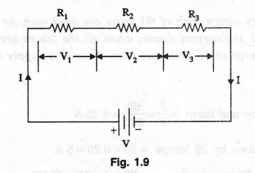
When resistors are connected as in figure 1.9 such that the same current passes through all of them, they are said to be in series.
RESISTORS IN SERIES
When
resistors are connected as in figure 1.9 such that the same current passes
through all of them, they are said to be in series.
Each
resistor has a voltage drop across it given by Ohm's law. Thus,
V1
= IR1; V2 = IR2 and V3 = IR3 …….
(10)
The
total drop in the three resistors put together is
V
= V1 + V2 + V3 = IR1 + IR3 ……
(11)
Thus
the circuit behaves as if a single resistor, R equal to R1 + R2
+ R3 is connected across the battery of V volts.
Figure
1.10 shows the equivalent of figure 1.9. Hence, the total effective resistance
of a number of resistors connected in series given by
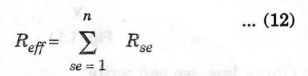
In
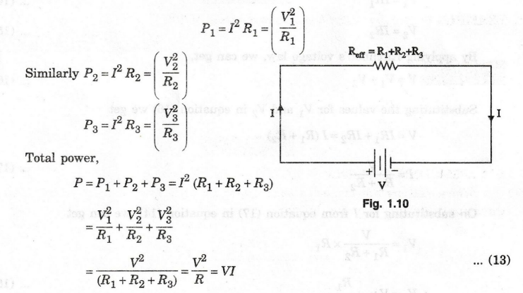
the circuit of figure 1.10 the power dissipated in R1 is given as
In
a series circuit,
1.
The same current flows through all the resistors.sups sidudative
2.
For each resistance, there will be a voltage drop according to Ohm's law.
3.
The sum of the voltage drop will be equal to the applied voltage.
Electric Circuit Analysis: Chapter - 1: Basic Circuit Analysis - DC : Tag: : Electric Circuit Analysis - Resistors in Series