Electrical Machines: Unit III: b.Testing of D.C. Machines
Retardation Test or Running Down Test
Testing of D.C. Machines
• This method is generally employed to shunt generators and shunt motors. From this method we can get stray losses. Thus if armature and shunt copper losses at any given load current are known then efficiency of a machine can be easily estimated.
Retardation
Test or Running Down Test
AU: Dec.-09, 15
•
This method is generally employed to
shunt generators and shunt motors. From this method we can get stray losses.
Thus if armature and shunt copper losses at any given load current are known
then efficiency of a machine can be easily estimated.
• The connections required for conducting this
test are shown in the Fig. 5.7.1.
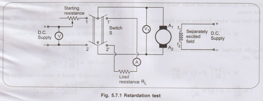
The
machine whose test is to be taken is run at a speed which is slightly above its
normal speed. The supply to the motor is cut off while the field is kept
excited. The armature consequently slows down and its kinetic energy is used in
supplying the rotational or stray losses which includes iron, friction and
winding loss.
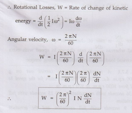
•
If I is the moment of inertia of the armature and w is the angular velocity.
Kinetic
energy of armature = ½ I ω2
Thus
if we want to find the rotational losses, the moment of inertia I and dN / dt must
be known.
These
quantities can be found as follows:
1. Determination of dN / dt
•
The voltmeter V1 which is connected across the armature will read
the back e.m.f. of the motor. We know that back e.m.f. is proportional to speed
so that voltmeter is calibrated to read the speed directly.
•
When motor is cut-off from the supply, the speed decreases. The time required
for definite decrease in speed is noted with the help of stop watch. A curve
showing variation between time and speed which is obtained from voltmeter which
is suitably calibrated is shown in the Fig. 5.7.2.
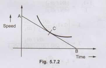
•
At any point C corresponding to normal speed, a tangent AB is drawn. Then
dN
/dt = OA (in r. p.m.) / OB (in seconds)
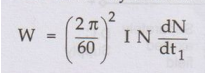
•
The value obtained from above can be substituted in the expression for W which
can give the rotational losses.
2. Determination of Moment of Inertia (I)
Method (a) - Using Flywheel
•
The armature supply is cut off and time required for definite change in speed
is noted to draw the corresponding curve as we have drawn in previous case.
This curve is drawn considering only armature of the machine. Now a flywheel
with known moment of inertia say I1 is keyed onto the shaft and the
same curve is drawn again. The slowing down time will be extended as combined
moment of inertia of the two is increased.
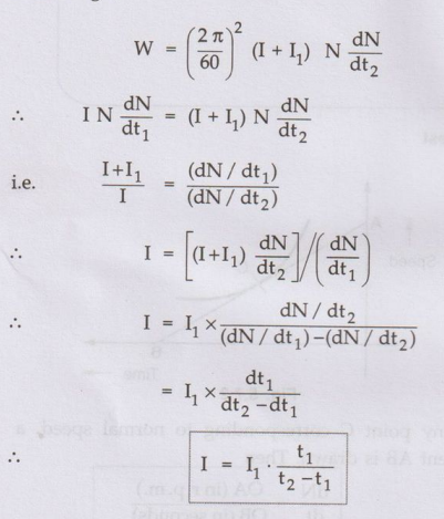
•
For any given speed (dN/dt1) and (dN/dt2) are determined
same as previous case. It can be seen that the losses in both the cases are
almost same as addition of flywheel will not make much difference to the
losses.
•
In the first case where flywheel is not there then,
Adding
the flywheel to the motor armature in second case we get,
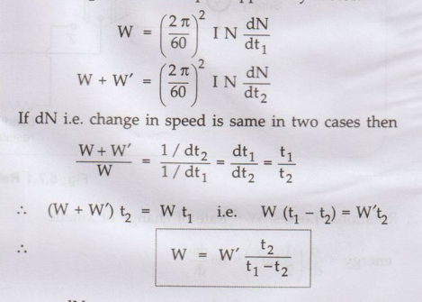
Method (b) - Without Using Flywheel
•
In this method time is noted for the machine to slow down by say 5 %
considering the armature alone. Then a retarding torque either mechanical or
electrical is applied. Preferably electrical retarding torque is applied and
time required to slow down by 5% is noted again. The method by which electrical
torque can be provided is shown in the Fig. 5.7.1 in which the switch S after
disconnecting from the supply is thrown to terminals 1'2'. The machine then
gets connected to a non-inductive load resistance RL. The power
drawn by this resistance will acts as a retarding torque on the armature which
will make it slow more quickly.
•
The additional loss in the resistance will be equal to product of ammeter
reading and the average reading of the voltmeter (for a fall of 5 % of
voltmeter reading, the time is noted.) The ammeter reading is also changing so
its average reading is taken. Thus the additional loss is Ia2
(Ra + R). Let t1 be the time when armature is considered
alone and t2 be the time when armature is connected across a load
resistance, V be average voltage across R and I be the average current and W'
is additional retarding electrical torque supplied by motor.
Here
dN / dt1 is rate of change in speed without extra load whereas dN /
dt2 is rate change in speed with extra dt2 electrical load which
provides retarding torque.
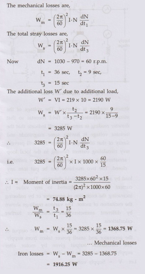
Ex. 5.7.1 A retardation test is carried out
on 1000 r.p.m. d.c. machine. The time taken for the speed to fall from 1030
r.p.m. to 970 r.p.m. is
i) 36 seconds with no excitation.
ii) 15 seconds with full excitation
iii) 9 seconds with full excitation
and the armature supporting an extra load of 10 A at 219 V.
Calculate: 1) The moment of inertia
of the armature in kg.m2. 2) Iron loss.
3) Mechanical loss at the mean
speed of 1000 r.p.m.
Sol. : Remember
that,
1.
When armature is slowing down and there is no excitation, then kinetic energy
is used to overcome mechanical losses only. Iron losses are absent as
excitation is absent.
2.
When excitation is given, kinetic energy is used to overcome both mechanical as
well as iron losses. Total called stray losses.
3.
If moment of inertia is in kg-m2, then loss of energy is in watts.
The
mechanical losses are,
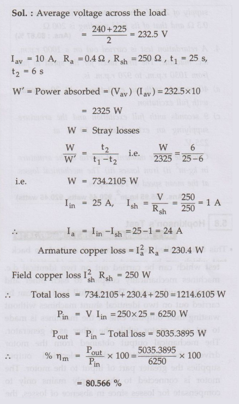
Ex. 5.7.2
A retardation test made on a separately-excited
d.c. machine as a motor. The induced voltage falls from 240 V to 225 V in 25
seconds on opening the armature circuit and 6 seconds on suddenly changing the
armature connection from supply to a load resistance taking 10 A (average).
Find the efficiency of the machine when running as a motor and taking a current
of 25 A on a supply of 250 V. The resistance of its armature is 0.4 Ω and that
of its field wi nding is 250 Ω. AU:
Dec.-09, Marks 8
Sol. :Average
voltage across the load
Review Questions
1. Describe the retardation test as applied to the d.c. shunt
machines.
AU: Dec.-15, Marks 8
2. How can stray losses of machine be determined with the
help of a retardation test with and without the knowledge of moment of inertia
?
3. A retardation test is made on a separately excited d.c.
machine as a motor. The induced voltage falls from 240 V to 220 V in 25 seconds
on opening the armature circuit and in 6 seconds on suddenly changing the
armature connection from supply to a load resistance which takes average
current of 10 A. Find the efficiency of the machine when running as a motor
taking a current of 25 A on a supply of 250 V. The resistance of its armature
is 0.3Ω and that of its field winding is 200 Ω. (Ans.: 80.67%)
4. A retardation test is carried out on a 1000 r.p.m. d.c.
machine. The time taken for the speed to fall from 1030 r.p.m. to 970 r.p.m.
is,
a) 40 seconds with no excitation b) 20 seconds with full
excitation c) 9 seconds with full excitation and the armature supplying an
extra load of 10 A at 225 V.
Calculate i) The moment of inertia of the armature in kg-m2
ii) Iron losses iii) The mechanical losses at the mean speed of 1000 r.p.m.
(Ans. : 55.95 kg-m2, 920.45 watts, 920.45 watts)
Electrical Machines: Unit III: b.Testing of D.C. Machines : Tag: : Testing of D.C. Machines - Retardation Test or Running Down Test
Related Topics
Related Subjects

Electrical Machines I
EE3303 EM 1 3rd Semester EEE Dept | 2021 Regulation | 3rd Semester EEE Dept 2021 Regulation