Digital Logic Circuits: Unit III: (c) Shift Registers
Ring Counters
Principle of operation, Logic Diagram, Truth Table, Waveform | Shift Registers
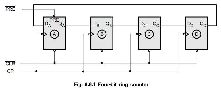
• Fig. 6.6.1 shows the logic diagram for four-bit ring counter.
Ring Counters
•
Fig. 6.6.1 shows the logic diagram for four-bit ring counter.
•
The Q output of each stage is connected to the D input of the next stage and
the output of last stage is fed back to the input of first stage.
•
The  followed by
 ![]() makes the output of first stage to 'I'
and remaining outputs are zero, i.e. QA is one and QB, QC,
QD are zero.
makes the output of first stage to 'I'
and remaining outputs are zero, i.e. QA is one and QB, QC,
QD are zero.
•
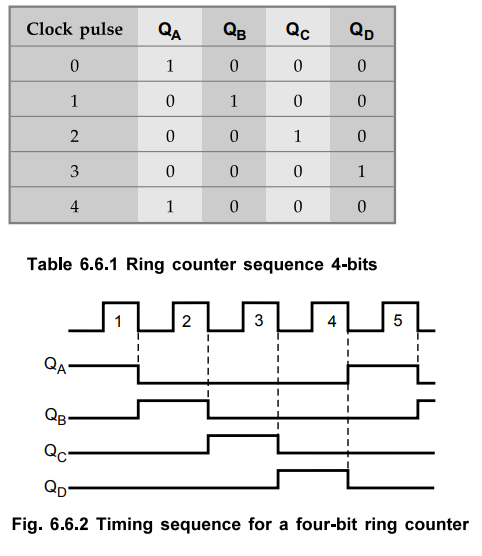
The first clock pulse produces QB = 1 and remaining outputs are zero.
•
According to the clock pulses applied at the clock input CP, a sequence of four
states is produced. These states are listed in Table 6.6.1.
•
1 is always retained in the counter and simply shifted 'around the ring',
advancing one stage for each clock pulse. In this case four stages of
flip-flops are used. So a sequence of four states is produced and repeated.
•
Fig. 6.6.1 gives the timing sequence for a four-bit ring counter.
•
The ring counter can be used for counting the number of pulses.
•
The number of pulses counted is read by noting which flip-flop is in state 1.
•
No decoding circuitry is required.
•
Since there is one pulse at the output for each of the N clock pulses, this
circuit is also referred to as a divide-by-N-counter or an N : 1 scalar.
•
Ring counters can be instructed for any desired MOD number, that is MOD-N ring
counter requires N flip-flops.
Ex.
6.6.1 Draw a six stage ring counter and explain its operation. Mention about
the use of presetting the counter.
AU
: CSE : Dec.-05, Marks 16
Sol.
:
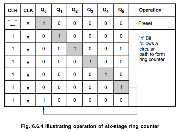
The Fig. 6.6.3 shows the six stage ring counter. The counter is present to
value (000001)2 by setting bit 0 = 1 and remaining bits = 0.

Operation
:
The Fig. 6.6.4 shows the operation of six-stage ring counter. On preset, FFO
(flip-flop 0) is set and FF1 to FF5 are reset. After each falling edge of the
clock contents of ring counter are shifted 1 bit from LSB to MSB.
Review Questions
1. Draw a six stage
ring counter and explain its operation.
AU CSE Dec.-05, Marks
16
2. Draw the timing
diagram of 4-bit ring counter.
AU CSE Dec.-04, Marks
2
3. Draw a 2-bit ripple
counter and convert this into a 2-bit ring counter.
AU CSE Dec.-05, Marks
2
Digital Logic Circuits: Unit III: (c) Shift Registers : Tag: : Principle of operation, Logic Diagram, Truth Table, Waveform | Shift Registers - Ring Counters
Related Topics
Related Subjects

Digital Logic Circuits
EE3302 3rd Semester EEE Dept | 2021 Regulation | 3rd Semester EEE Dept 2021 Regulation