Transmission and Distribution: Unit III: (a) Mechanical Design of Transmission Lines
Sag Template and Tower Spotting
Generally two types of towers are used to support the overhead transmission lines which are, 1. The standard or straight run or intermediate tower. 2. The angle or anchor or tension tower.
Sag Template and Tower
Spotting
Generally two types of towers are used
to support the overhead transmission lines which are,
1. The standard or straight run or
intermediate tower.
2. The angle or anchor or tension tower.
The standard towers are used for
straight rim of the line under normal conditions. While the positions where
line is to be turned, curves and other points where support will be under high
mechanical stress, the angle or tension towers are used. Thus design of tension
towers is such that they can withstand large mechanical stress. The height of
the towers and position of the towers is an important part of the mechanical
design of the transmission lines.
For locating the tower positions, for
normal spans and for standard towers, the sag and the nature of the conductor
curve are calculated, under expected load conditions and plotted on a thin
stiff plastic sheet. Such a graph is called sag template. The minimum ground
clearance curve can be plotted parallel to the conductor curve on the template.
The tower footing line can also be drawn on the template which helps to locate
the towers, so that minimum ground clearance is maintained. Various other
curves at some other temperatures like 20 °C and 50 °C are also plotted on the
template. The axis of the template is placed vertically between the two tower
lines. The horizontal distances give span lengths while vertical distances give
the sags.
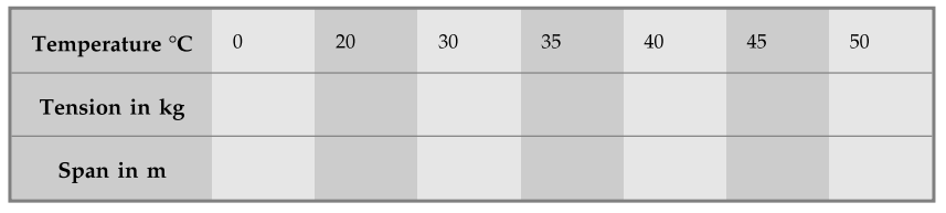
For preparing the sag template, the
table for the sag tension is prepared as shown below,
A typical sag template is shown in the
Fig. 4.9.1.
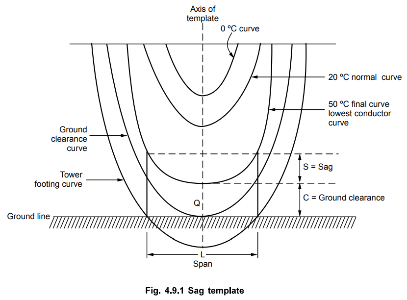
The ground clearance curve is tangential
to the ground level at point Q. The tower footing line intersects the points on
the ground where towers are situated. This line helps to fix up position of
towers, with minimum ground clearance of 'C' is maintained throughout. The
clearance to ground depends on the operating voltage and specified as per the
Indian electricity rules. Taking the rules into consideration, the template is
prepared.
While using the sag template, the
profile of the land is drawn on the paper. The spans are indicated by tentative
vertical lines. Then the transparent sag template is placed on the route drawn.
It is then adjusted such that the ground clearance curve just touches the
profile. At this position, the tower footing line gives the positions of the
towers. The actual conductor curve is then represented by lowest conductor
curve on the template. The template can be used for any shape of ground profile
and not only for plane ground. The Fig. 4.9.2 shows the use of sag template to
locate the towers.
The points A and B, which are the
intersection points of tower footing line with land profile, give the positions
of the towers.
Following objectives can be achieved
using the sag template,
1. Safe ground clearance is maintained
throughout.
2. Choice of span and height of towers
with good accuracy.
3. Positions of towers.
4. Towers with almost equal heights,
weight and hence cost.
5. Towers which carry almost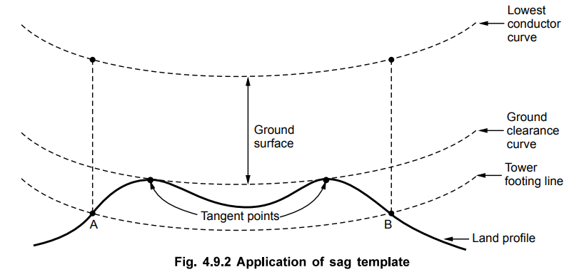 equal
loads.
equal
loads.
6. Economical layout of the system.
It should be noted that for each new
line conductor, a new template is preferred.
Review Question
1. What is sag template ? What objectives can be achieved using the
sag template?
AU : Dec.-17, Marks 6
Transmission and Distribution: Unit III: (a) Mechanical Design of Transmission Lines : Tag: : - Sag Template and Tower Spotting
Related Topics
Related Subjects

Transmission and Distribution
EE3401 TD 4th Semester EEE Dept | 2021 Regulation | 4th Semester EEE Dept 2021 Regulation