Linear Integrated Circuits: Unit III: Applications of Op-amp
Schmitt Trigger using Op-amp
Working Principle, Pulse, Circuit Diagram, Equation, Applications, Solved Example Problems | Operational amplifier
In a basic comparator, a feedback is not used and the op-amp is used in the open loop mode. As open loop gain of op-amp is large, very small noise voltages also can cause triggering of the comparator, to change its state.
Schmitt Trigger using Op-amp
In
a basic comparator, a feedback is not used and the op-amp is used in the open
loop mode.
As
open loop gain of op-amp is large, very small noise voltages also can cause
triggering of the comparator, to change its state.
Such
a false triggering may cause lot of problems in the applications of comparator
as zero crossing detector.
The
comparator circuit used to avoid such unwanted triggering is called
regenerative comparator or Schmitt trigger, which basically uses a positive
feedback.
1. Inverting Schmitt Trigger
The
Fig. 3.28.1 shows the basic Schmitt trigger circuit.

The
inverting mode produces opposite polarity output. This is fed back to the
non-inverting input which is of same polarity as that of output. This ensures
positive feedback.
When
Vin is slightly positive than Vrefz the output gets driven into
negative saturation at - Vsat level.
When
Vin becomes more negative than -Vref, then output gets
driven into positive saturation at + Vsat level.
Thus
output voltage is always at + Vsat or - Vsat but the
voltage at which it changes its state now can be controlled by the resistance R1
and R2. Thus Vref can be obtained as per the requirement.
Now
R1 and R2 forms a potential divider and we can write,
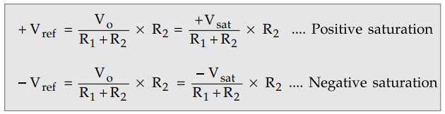
+
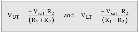
Vref is for positive saturation when Vo = +Vsat
and is called upper threshold voltage denoted as VUT.
-
Vref is for negative saturation when Vo = - Vsat and
is called lower threshold voltage denoted as VLT.
The
values of these threshold voltage levels can be determined and adjusted by
selecting proper values of R1 and R2.
The
output voltage remains in a given state until the input voltage exceeds the
threshold voltage level either positive or negative.
The
Fig. 3.28.2 shows the graph of output voltage against input voltage. This is
called transfer characteristics of Schmitt trigger.
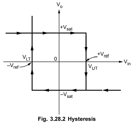
The graph indicates that once once the output changes its state, it remains there indefinitely until the input voltage crosses any of the threshold voltage levels. This is called hysteresis of Schmitt trigger. The hysteresis is also called dead band or dead zone.
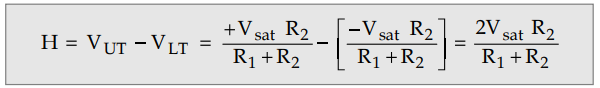
The difference between VUT and VLT is called width of the hysteresis denoted as H.
The
Schmitt trigger eliminates the effect of noise voltage.
The
noise voltages less than the hysteresis H, cannot cause triggering.
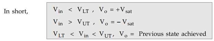
For positive Vin greater than VUT the output becomes -Vsat and for negative Vin less than VLT, the output becomes + Vsat this is called inverting Schmitt trigger.
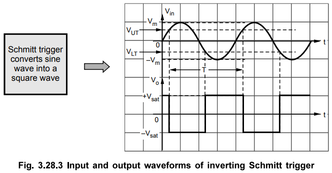
The
waveforms are shown in the Fig. 3.28.3.
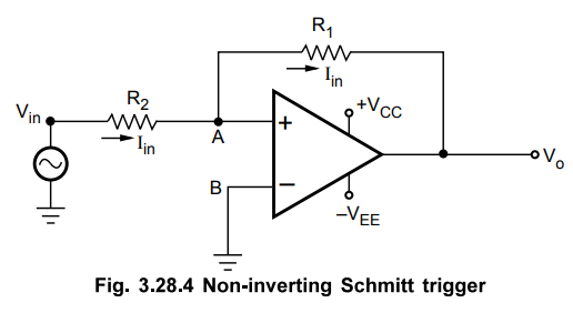
2. Non-inverting Schmitt Trigger
The
Fig. 3.28.4 shows the non-inverting Schmitt Schmitt trigger circuit. The input
is applied to the non-inverting input terminal of the op-amp.
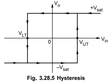
To
understand the working of the circuit, let us assume that the output is positively
saturated i.e. at +Vsat. This is fed back to the non-inverting input
through R1. This is a positive feedback.
Now
though Vin is decreased, the output continues its positive
saturation level unless and until the input becomes more negative than VLT.
At lower threshold, the output changes its state from positive saturation +Vsat
to negative saturation -Vsat. It remains in negative
saturation till Vin increases beyond its upper threshold level VUT.
The transfer characteristics is shown in the Fig. 3.28.5.
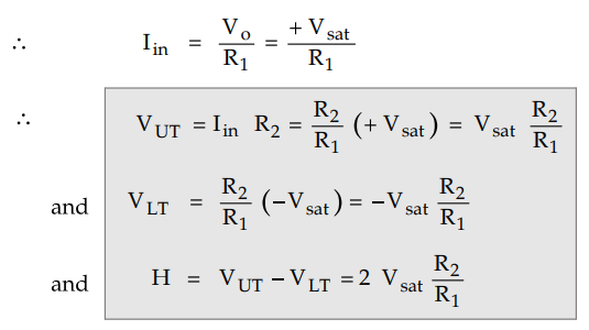
VA
= Voltage at point A = Iin R2 = VUT
As
op-amp input current is zero, Iin entirely passes through R1.
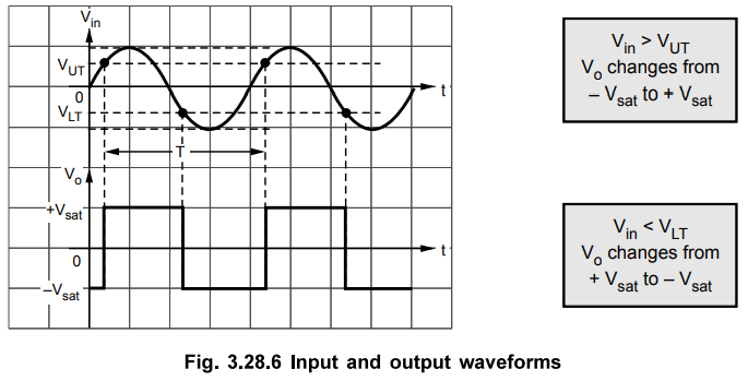
If
sinusoidal input is applied to the non-inverting Schmitt trigger, the input and
output waveforms can be shown as in the Fig. 3.28.6.
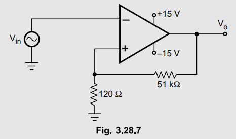
Example
3.28.1 For a Schmitt trigger shown in the Fig.
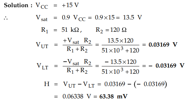
3.28.7, calculate threshold voltage levels and hysteresis. Assume Vsat =0-9
VCC.
Solution :
3. Schmitt Trigger Applications
One
important application of trigger is sine to square wave converter. It can be
used to eliminate comparator chatter in signal shaping and in ON/OFF control.
It is a building block of relaxation oscillators.
a.
Schmitt Triggers for Eliminating Comparator Chatter
Chattering
can be defined as production of multiple output transition as the input signal
swings through the threshold region of a comparator.
This
happens due to the fact that a.c. noise is present in the practical circuits.
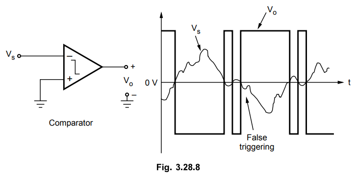
Fig.
3.28.8 shows input signal with a.c. noise and how comparator output chatters.
Even if noise is very less, it takes a very small noise spike to cause chatter
due to high comparator gains.
This
problem can be solved by using trigger circuits. This is because they exhibit
hysteresis.
In
case of hysteresis, as soon as the input signal crosses the present threshold
level once, the output changes its state and activates the other threshold
level, so that the input signal must swing back to the new threshold in order
to make the output of the circuit to change its state again.
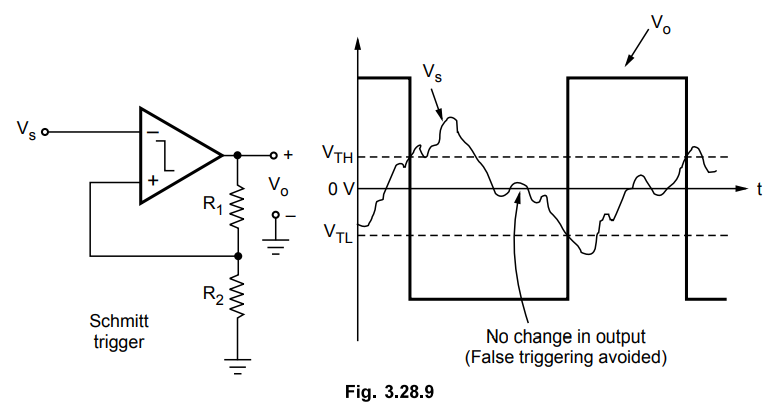
Refer
Fig. 3.28.9, by making hysteresis width greater than the maximum peak amplitude
of noise, a dead zone is created such that noise within this zone no longer
causes multiple output transitions.
b.
Schmitt Triggers in ON/OFF Controllers
In
ON/OFF controller, such as temperature controller, when temperature is below
setpoint heater is made ON and when it is above setpoint heater is made OFF.
Now
consider that temperature is just below the set point and heater is ON.
As
soon as the temperature reaches the set point, the comparator which is
controlling the heater makes it OFF.
The
smallest temperature drop following the heater OFF will make comparator to go
in its activate state and switch on the heater. As a result, the heater will be
cycled ON and OFF by the comparator at a rapid pace. This is not desirable.
Temperature
usually need not be regulated to such a sharp degree. By allowing a dead band
of a few degrees we can ensure a comfortable environment and reduce heater
cycling significantly. This is possible by introducing hysteresis in the
comparator using Schmitt trigger.
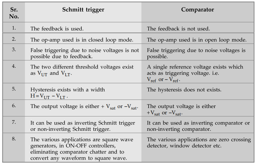
4. Comparison of Schmitt Trigger and Comparator
The various differences and similarities between Schmitt trigger and comparator are given in the following table.
Example
3.28.2 Design and draw the circuit of Schmitt trigger with
VUT - 25 mV, VLT = -25 mV, Vin = 1 Vp_p,
voltage swings ± 14 V. Calculate R1 R2 and ROM
Solution
:
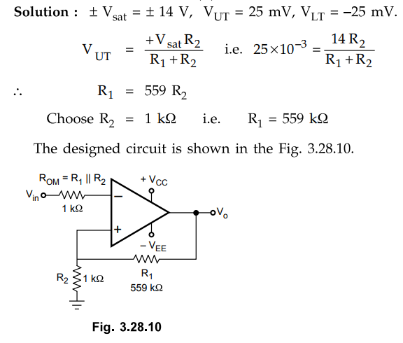
Choose
R2 = 1 kΩ i.e. R1 = 559 kΩ
The designed circuit is shown in the Fig. 3.28.10.
Review Questions
1. Explain the working of inverting Schmitt trigger. Derive the
equation for the trigger points.
2. Explain the working of noninverting Schmitt trigger. Derive
the equation for the trigger points.
3. Design Schmitt trigger having upper and lower threshold of 120
mV. Input to this circuit is 1 V peak to peak triangular wave cf 100 Hz. Draw
the hysteresis loop.
[Ans.: Vat = ± 15 V, R1 = kΩ, R2
= 1 kΩ]
4. What is the difference between basic comparator and Schmitt
trigger.
5. With a neat circuit diagram, explain the working of Schmitt
trigger using op-amp.
May-15, 16, Marks 8
Linear Integrated Circuits: Unit III: Applications of Op-amp : Tag: : Working Principle, Pulse, Circuit Diagram, Equation, Applications, Solved Example Problems | Operational amplifier - Schmitt Trigger using Op-amp
Related Topics
Related Subjects

Linear Integrated Circuits
EE3402 Lic Operational Amplifiers 4th Semester EEE Dept | 2021 Regulation | 4th Semester EEE Dept 2021 Regulation