Linear Integrated Circuits: Unit III: Applications of Op-amp
Second Order Low Pass Butterworth Filter using Op-amp
Operational amplifier
The practical response of the filter must be very close to an ideal one. In case of low pass filter, it is always desirable that the gain rolls off very fast after the cut off frequency, in the stop band.
Second Order Low Pass Butterworth Filter
April-02,
May-06, 07, 09, 11, 17, Dec.-03, 11, 15, 17
The
practical response of the filter must be very close to an ideal one. In case of
low pass filter, it is always desirable that the gain rolls off very fast after
the cut off frequency, in the stop band. In case of first order filter, it
rolls off at a rate of 20dB/decade. In case of second order filter, the gain
rolls off at a rate of 40 dB/decade. Thus, the slope of the frequency response after
f = fH is -40 dB/decade, for a second order low pass filter.
A
first order filter can be converted to second order type by using an additional
RC network as shown in the Fig. 3.7.1.
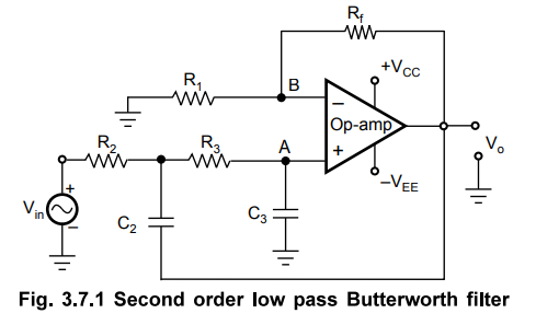
The
cut off frequency fH for the filter is now decided by R2, C2,
R3 and C3. The gain of the filter is as usual decided by
op-amp i.e. the resistance R1 and Rf.
1. Analysis of the Filter Circuit
For
deriving the expression for the cut off frequency, let us use the Laplace
transform method.
The
input RC network can be represented in the Laplace domain as shown in Fig.
3.7.2.
Now
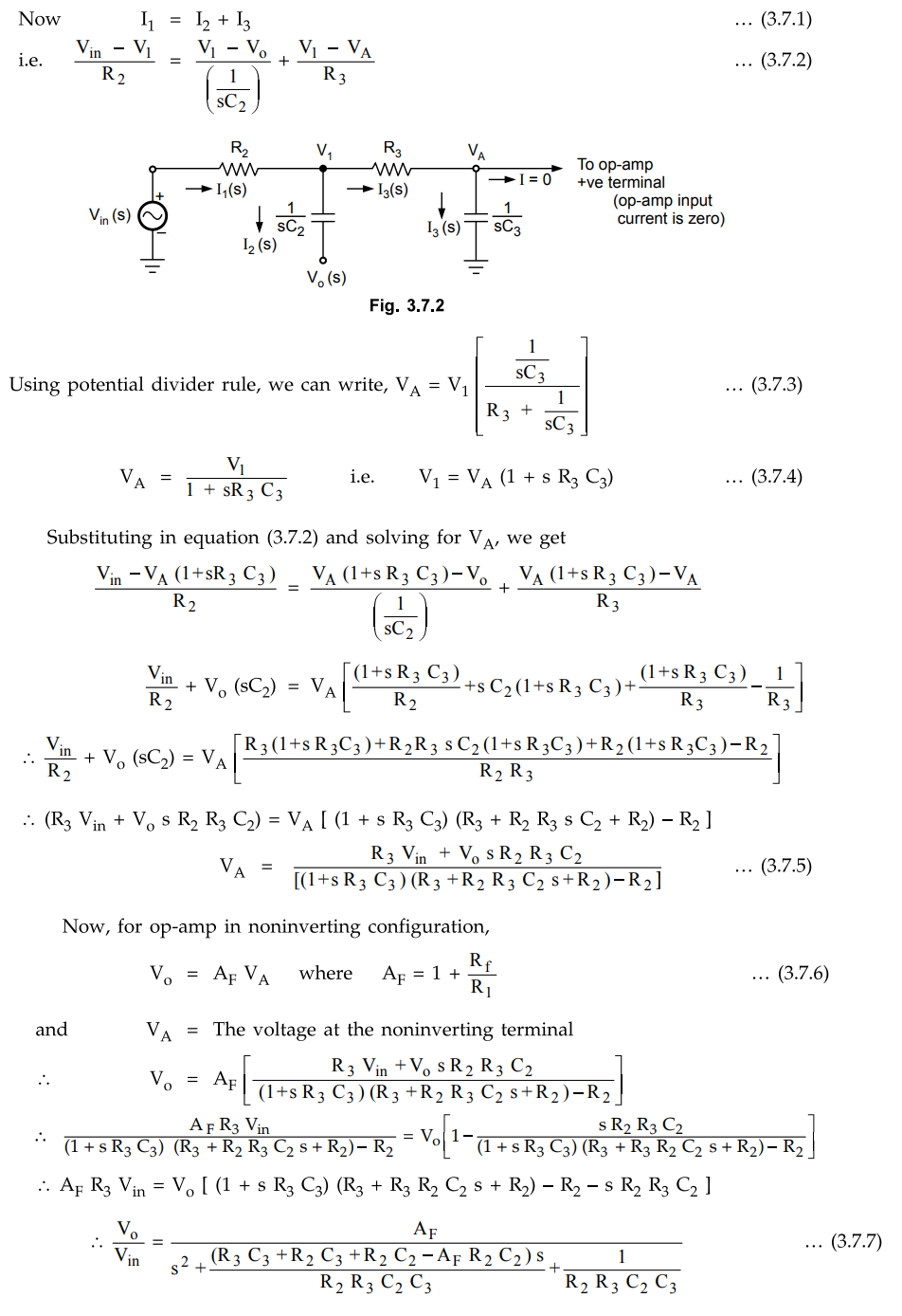
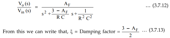
As
the order of s in the gain expression is two, the filter is called second order
filter. The standard form of the transfer function of any second order system
is
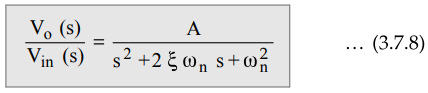
where
A = Overall gain, ᶓ = Damping of system, ωn - Natural frequency of
oscillations
Comparing
equation (3.7.7) and equation (3.7.8), we can say that
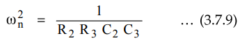
In
case of filters, this frequency is nothing but the cut-off frequency, ωH
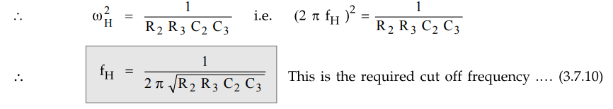
This
is the required cut off frequency .... (3.7.10)
Replacing
s by jω, the transfer function can be written in the frequency domain and
hence, finally, can be expressed in the polar form as,
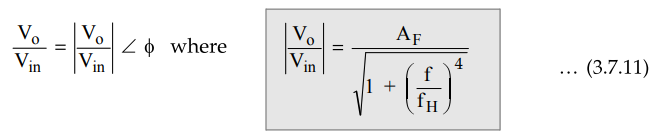
and AF = Gain of filter in pass band
, f - Input frequency in Hz
fH
= High cut-off frequency in Hz
The
frequency response is shown in Fig. 3.7.3.
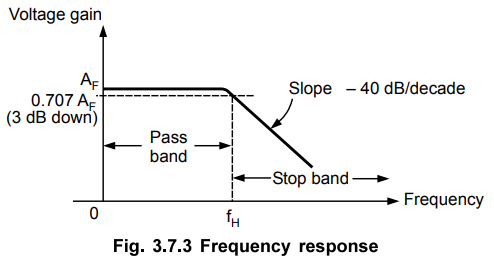
At
the cut-off frequency, fH' the gain is 0.707 AF i.e. 3 dB down from its 0 Hz
level. After, fH(f > fH), the gain rolls off at a rate
of 40 dB/decade. Hence, the slope of the response after fH is - 40 dB/decade.
2. Design Steps
The
design steps for second order low pass Butterworth filter are
1)
Choose the cut-off frequency fH.
2)
The design can be simplified by selecting R2 = R3 = R and
C2 = C3 = C.
And
choose a value of C less than or equal to 1 µF.
3)
Calculate the value of R from the equation,
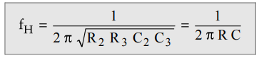
4)
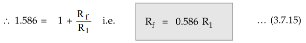
As R2 = R3 = R and C2 = C3 = C, the
pass band voltage gain AF = (1 + Rf/R1) of the
second order low pass filter has to be equal to 1.586.
Note
For R2 = R3 = R and C2 = C3 = C,
the transfer function takes the form.
Now,
for second order Butterworth filter, the middle term required is √2 = 1.414,
from the normalised Butterworth polynomial.
3
- AF = √2 = 1.414 i.e AF
= 1.586 …. (3.7.14)
Thus,
to ensure the Butterworth response, it is necessary that the gain AF
is 1.586.
Key
Point Hence, choose a value of R1 ≤ 100 kΩ
and calculate the corresponding value of Rf
The
frequency scaling method discussed earlier for first order filter is equally
applicable to the second order filter.
Example
3.7.1 Design a second order Butterworth low pass
filter having upper cut-off frequency of 1 kHz.
Solution
:
Step
1 :
fH = 1 kHz
Step
2 :
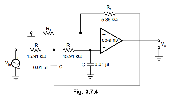
Choose C2 = C3 = C = 0.01 µF
Step
3 :
Choose R2 = R3 = R
fH
= 1 / 2πRC i.e. R = 15.915 kΩ
Step
4 :
For Butterworth response,
Rf
= 0.586 R1
Choose
R1 = 10 kΩ
Rf
= 5.86 kΩ
Use
a 10 kΩ potentiometer for precise adjustment of Rf.
The
designed circuit is shown in the Fig. 3.7.4.
Example
3.7.2 Design a second order Butterworth low pass filter with cut off
frequency 2 kHz.
May-17,
Marks 6
Solution
:
Refer Ex. 3.7.1 for the procedure and verify the component values as,
C
= 0.01 µF, R = 7.95 kΩ , R1 = 10 kΩ, Rf = 5.86 kΩ.
Review Question
1. Draw the circuit
diagram of a second order Butterworth active low pass filter and derive an
expression for its transfer function.
Linear Integrated Circuits: Unit III: Applications of Op-amp : Tag: : Operational amplifier - Second Order Low Pass Butterworth Filter using Op-amp
Related Topics
Related Subjects

Linear Integrated Circuits
EE3402 Lic Operational Amplifiers 4th Semester EEE Dept | 2021 Regulation | 4th Semester EEE Dept 2021 Regulation