Microprocessors and Microcontrollers: Unit IV: (d) Serial Data Transfer (USART) 8251
Serial Communication Supported by 8085
Serial Data Transfer (USART) 8251
The 8085 microprocessor communicates serially using two lines : SOD and SID. The Serial Output Data (SOD) line is used to send 1-bit data on the SOD Pin of 8085 and RIM instruction is used to receive 1-bit data on the SID pin of 8085.
Serial Communication Supported by 8085
The
8085 microprocessor communicates serially using two lines : SOD and SID. The
Serial Output Data (SOD) line is used to send 1-bit data on the SOD Pin of 8085
and RIM instruction is used to receive 1-bit data on the SID pin of 8085.
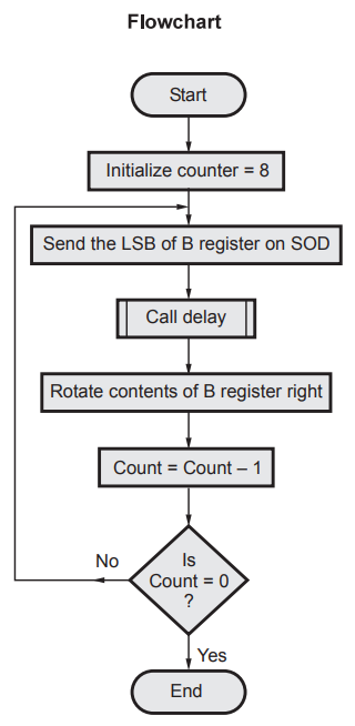
Lab Experiment 11.1.1 : Output byte
from SOD pin.
Statement :
Write a program to output contents of B register LSB to MSB on the SOD pin.
Source
program
MVI
C, 08H ; Initialize count with 8
BACK
: MOV A,B ;
RRC
; Rotate B register contents right
MOV
B,A ; Save contents of register B
JNC
SKIP ; If no carry skip
MVI
A, C0H
SIM
; If carry, send high on SOD
JMP
NEXT
SKIP
: MVI A, 40H
SIM
; If no carry, send high on SOD
NEXT
: CALL DELAY ; Wait for specific time
DCR
C ; Decrement count by 1
JNZ
BACK ; if count = 0, if not repeat
HLT
; Stop program execution
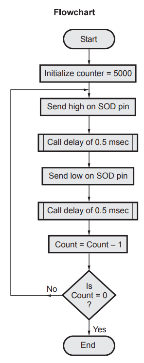
Lab Experiment 11.1.2 : Output square
wave from SOD pin.
Statement :
Write a program to output square wave of 1 kHz frequency on the SOD pin of 8085
for 5 seconds. Operating frequency of 8085 is 2 MHz.
LXI
SP, 27FFH ; Initialize stack pointer
LXI
H, 2000H ; Initialize counter with count
;
5000.
BACK
: MVI A, C0H
SIM
; Send high on SOD pin
CALL
DELAY ; Wait for 0.5 msec (Refer delay
;
program of program 46)
MVI
A, 40 H ; Send low on SOD pin
CALL
DELAY ; Wait for 0.5 msec
DCX
B ; Decrement count by 1
MOV
A, C
ORA
B ; Check if count = 0
JNZ
BACK ; If not, repeat
HLT
; Stop program execution
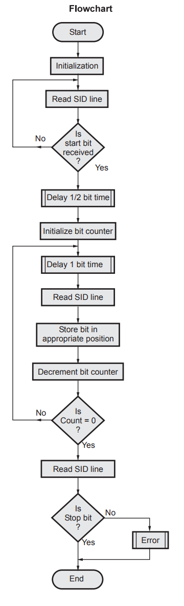
Lab Experiment 11.1.3 : Receive ASCII
character through SID pin.
Statement :
An ASCII character is being received on SID pin of 8085. Write a program in
assembly language of 8085 to assemble this character and store it in memory.
Write comment for each instruction.
Source
program
LXI
SP, 27FFH
LXI
H, 2000H ; Memory pointer
RIM ; Read SID
ANI
80H ; Check D7 bit of Accumulator
CALL
Delay ; 1/2 bit time delay for stop bit
MVI
B, 08H ; Initialize bit counter
MVI
D,00H ; Clear data register
UP1
ALL Dealy ; 1bit time
RIM
; Read SID line
ANI
80H ; Mask bits B6-B0
ORA
D ; OR data bit with previous
;
bits
RRC
MOV
D, A ; Store data bit at
;
appropriate position
DCR
B
JNZ
UP1
RLC
; Shift left to correct result
MOV
M, A ; Store result
RIM
; Read stop bit
ANI
80H
CZ
error ; If not stop bit call error
HLT
; Terminate program.
From
above examples it is clear that 8085 has two pins for serial communication.
However, it does not support built-in serial to parallel converter and
parallel-to-serial converter. To transmit byte data it is necessary to convert
byte into eight serial bits. This can be done by using the parallel to serial
converter. Similarly at the reception these serial bits must be converted into
parallel 8 bit data. The serial to parallel converter is used to convert serial
data bits into the parallel data.
In
8085, we have to achieve this with the help of programming as done in previous
examples.
The
Intel has designed special devices for this purpose are called Universal
Asynchronous Receiver-Transmitter (UART). The devices which provide synchronous
as well as asynchronous transmission and reception are called Universal
Synchronous Asynchronous Receiver-Transmitter. A good example of UART is 8250
and USART is 8251. These devices are software programmable for number of data
bits, parity and number of stop bits. In the next section we discuss IC 8251
(USART).
Review Questions
1. Compare parallel
and serial type of data transfer.
2. Write a short note
on serial communication supported by 8085.
3. Write a program to output square wave of 1 kHz frequency on the SOD pin of 8085 for 5 seconds.
Microprocessors and Microcontrollers: Unit IV: (d) Serial Data Transfer (USART) 8251 : Tag: : Serial Data Transfer (USART) 8251 - Serial Communication Supported by 8085