Electric Circuit Analysis: Unit I: b. Basic circuits analysis
Series Combination of Resistors
with Circuit Diagram, Equation, Solved Example Problems, Applications, Disadvantage
In a practical case we may have many resistors. We have to connect them for getting desired resistance. The resistors can be connected in the following three fashions. (a) Series combination (b) Parallel combination (c) Series - parallel combination
COMBINATION
OF RESISTORS
In
a practical case we may have many resistors. We have to connect them for
getting desired resistance. The resistors can be connected in the following
three fashions.
(a)
Series combination
(b)
Parallel combination
(c)
Series - parallel combination
Series Combination
If
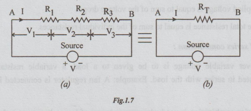
the resistors are connected end to end, the combination is said to be series.
The voltage source (energy source) is connected between the free ends. Refer
the Fig. 1.7 (a). The resistors R1, R2 and R3
are all connected end to end. The free terminals A and B are connected to the
voltage source.
Since
there is only one closed loop, only one current flows, i.e., the source current
flows through all the elements. In other words if the current is same through
all the resistors, the combination is called series combination.
There
is a voltage drop across each resistor.
To find equivalent resistance:
Let
V = applied voltage,
I
= source current = current through each element
V1,
V2, V3 are the voltages across R1, R2
and R3 respectively.
By
ohms law V1 = IR1
V2
= IR2 and V3 = IR3
But
V = V1+ V2+ V3
=
IR1 + IR2+ IR3
=
I (R1 + R2+ R3)... (i)
If
RT be the equivalent resistance of the combination, its value should
be such that the same current as above flows through it when applied voltage is
same.
By
ohm's law V = I × RT ....(ii)
From
the equations (i) and (ii) we get
RT
= R1 + R2+ R3
From
the series combination the following salient points are to be remembered.
(i)
In the series combination, the current is same through all the elements. In
other words, if the current through the elements is same then the combination
is series combination
(ii)
The voltage is distributed. The voltage across the resistor is proportional to
its resistance.
(iii)
The equivalent resistant RT (also known as total resistant RT)
is greater than the greatest individual resistance of that combination.
(iv)
Powers are additive
(v)
Applied voltage is equal to sum of the voltage drops
(vi)
The total resistance is equal to sum of the individual resistances.
Applications of series combination:
1.
Wherever variable voltage is to be given to a load, a variable resistance
(rheostat) is connected in series with the load. Example: A fan regulator is
connected in series with the fan.
2.
The series combination is used where many lamps of low voltages are to be
operated on the main supply. Example: Decoration lights.
3.
When a load of low voltage is to be operated on a high voltage supply, a fixed
value of resistance is connected in series with the load.
Disadvantage of series circuits:
(i)
If any break takes place at any point in a circuit, there will not be any
current flow. Hence the entire circuit becomes useless.
(ii)
Suppose that there are two lamps each rated 230 Volts, 100 watts and let the
supply voltage be 230 volts. If the two lamps are connected in series we
require a total voltage of 2 × 230 = 460 volts for satisfactory operation. But
the available voltage is only 230 volts. If the combination is series connected
to 230 volts, the lamps will be operating with the dim light. It is not
desirable. In each and every house, in India the single phase supply is only
230 volts. Hence series circuits is not practicable for lighting circuits.
(iii)
Take examples of two Bulbs A and B. A rated 115 volts and 100 watts and B rated
115 volts, 50 watts. If these two are connected in series across a supply
voltage of 230 volts, no damage will take place but operation cannot be with
efficiency.
Note:
1.
If there are n resistors each of value of R ohms in series the total resistance
is given by RT = n × R.
2.
If there are two resistors R1 and R2 in series connected
across a supply voltage of V,
V1
= VR1 / R1 + R2
And
V2 = VR2 /R1 + R2
WORKED EXAMPLES ON SERIES RESISTIVE CIRCUITS
Example 1 The lamps in a set of Christmas tree lights are connected in series. If there are 20 lamps and each lamp has resistance of 25Ω, calculate the total resistance of the set of lamps and hence calculate the current taken from a supply of 230 volts.
Solution: Supply voltage = V = 230 volts
Resistance of each lamp R = 25 Ω
No. of lamps in series = n = 20
Total resistance RT = n R
= 20 × 25 = 500 Ω
Current from supply I = V/RT = 230 / 500 = 0.46 A
Example 2 The field coil of a d.c. generator has a resistance of 250 Ω and is supplied from a 220 V source. If the current in the field coil is to be limited to 0.44A, calculate the resistance of the resistor to be connected in series with the coil.
Solution:
Source voltage = V = 220 volts
Field coil resistance = Rf = 250 Ω
Let the resistance of the resistor in series with Rf be R Ω
Total resistance RT = Rf + R = 250+ R
Given that, Current I = 0.44 A
By Ohm's law RT = V/I
= 220/0.44 = 500
⇒ = 250+ R 500 Ω
R = 500-250 =250 Ω
Ans: R =250 Ω
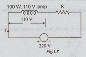
Example 3 An incandescent lamp is rated for 110V, 100W. Using a suitable resistor how can you operate this lamp on 220 V mains.
Solution:
Rated current of the lamp I = power / voltage
= 100 / 110 = 10 / 11A
For satisfactory operation of the lamp, current of 10 / 11 A should flow.
When the voltage across lamp is 110V, then the remaining voltage must be across R.
Supply voltage V = 220 volts
Voltage across R = V - 110 volts
i.e.,VR = 220-110
= 110 V
By Ohm's law, VR = IR
⇒ 110 = 10/11 R
Ans: R = 121 Ω
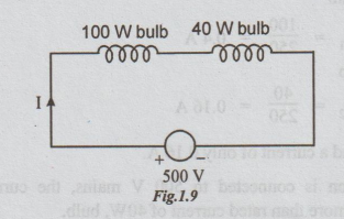
Example 4 A 100 W, 250 V bulb is put in series with a 40W, 250 V bulb across a 500 V supply. What will be the current drawn? What will be the power consumed by each bulb? Will such a combination work?
Solution:
Resistance = (voltage)2 / power
Let R1 = Resistance of 100 W bulb
R2 = Resistance of 40 W bulb
From the details of rating
R1= (250)2/100 = 625 Ω
R2 = (250)2 /40 = 1562.5 Ω
When the bulbs are put in series
RT = R1 + R2
= 625+ 1562.5
= 2187.5 Ω
Voltage across the bulbs
V = 500 volts (given)
Current I = V/RT
= 500 / 2187.5 = 0.2286 A
Power consumed by 100 W bulb
P1 = I2R1
= (0.2286)2 (625)
= 32.66 W
Power consumed by 40 W bulb
P2 = I2R2
= (0.2286)2 (1562.5)
= 81.7 W
When 40W bulb will try to draw a power of 81.63 W, its filament will be overheated and will burn. Hence such combination will not work.
Note: Another way of reasoning.
Rated current of 100 W bulb
I1 = 100/250== 0.4 A
Rated current of 40W bulb
I2 = 40/250 =0.16 A
That is, 40 W can withstand a current of only 0.16 A.
But when the combination is connected to 500 V mains, the current through the both bulbs theoretically is 0.2286A. It is more than rated current of 40W, bulb.
Due to this high current, the filament of 40W bulb gets overheated and will burn. It makes the circuit open.
Electric Circuit Analysis: Unit I: b. Basic circuits analysis : Tag: : with Circuit Diagram, Equation, Solved Example Problems, Applications, Disadvantage - Series Combination of Resistors
Related Topics
Related Subjects

Electric Circuit Analysis
EE3251 2nd Semester 2021 Regulation | 2nd Semester EEE Dept 2021 Regulation