Electric Circuit Analysis: Unit I: b. Basic circuits analysis
Series-Parallel Circuits Combination of Resistors
with Circuit Diagram, Equation, Solved Example Problems
Series-Parallel Circuits Combination of Resistors with Circuit Diagram, Equation, Solved Example Problems, Applications, Disadvantage
Series-Parallel
Circuits
A
practical situation may arise where the combination of resistances must be of
this type.
For
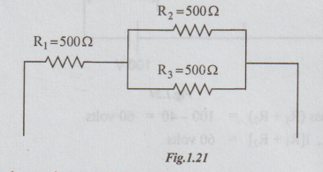
example, suppose that a radio requires 750 Ω resistances. Assume that three
resistors of each 500 Ω are available. If these are in series we get a resistor
of 1500 Ω Q. If all are in parallel we get a resistor of 500/3 = 166.7 Ω
(approximately). But we need neither 1500 Ω nor 166.7 Ω.
Suppose
that two are in parallel. Their equivalent is 500 / 2 = 250 Ω.
If
this combination is in series with 500 2 resistor, the equivalent is 500 + 250
= 750 Ω.
It is our desired value
It
is the example of simplest series - parallel combination.
Note:
For obtaining the total resistance in the series parallel combination the
following steps are useful.
(i)
Try to get finally series combination. Then their sum is total resistance like
case (a) OR
(ii)
Try to get finally parallel combination which can be simplified like case (b).
WORKED EXAMPLES ON SERIES-PARALLEL CIRCUITS
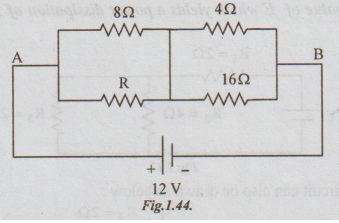
Example 1 Find the voltage across R1 and R2

Also find the value of R3
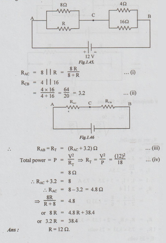
Solution: For understanding easily the given circuit can be re-drawn as shown below:
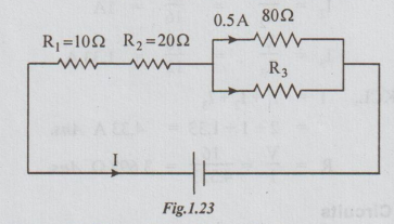
By Ohm's law, Voltage across 80Ω = 40 volts
As 80 Ω and R3 are in parallel, VR3 = 40 volts
i.e., Voltage across R3 = 40 volts
Let the equivalent of parallel combination of 80 and R3 be Rp.
Hence the circuit becomes as
voltage across (R1 + R2) = 100 - 40 = 60 volts
i.e., I[R1 + R2] = 60 volts
I = 60/ R1+R2 = 60/10+20 = 2A
By ohm's law VRI = IR1=2 ×10=20 volts
VR2 = IR2 = 2 × 20 = 40 volts
By KCL, I = 0.5+IR3
⇒ IR3 = I-0.5 = 2-0.5 = 1.5A
R3 = VR3/IR3 = 40/1.5 = 26.7Ω
Ans: (i) VR1 = 20volts
(ii) VR2= 40volts
(iii) R3 = 26.7 Ω
Example 2 Find V in the circuit in fig. 1.25
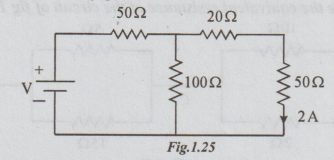
Solution: Re-drawing the circuit given, we obtain the following fig. 1.25
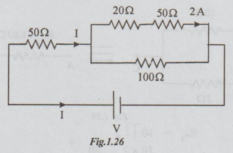
Given that, I20 = I50 = 2A
By ohm's law, V20 = I20 × 20 = 2× 20 = 40 volts
And V50= I50 × 20 = 2 × 50 =100 volts
V20 + V 50 = 40 + 100 = 140 volts
⇒ V70 = 140 volts
As 100 Ω and (20+ 50) are in parallel.
V100 = V70 = 140
⇒ By ohm's law, I100 = 140/100 = 1.4A
By KCL, I= I100 +I70 = 1.4 +2 = 3.4 A
Let RP be the equivalent of parallel combination of 70 and 100Ω
Rp = 70 × 100/ 70 + 100 = 41.2 Ω

50 Ω and 41.2 are in series.
Rtotal = 50 + 41.2 = 91.2 Ω
V = IRtotal
= 3.4 × 91.2
= 310 volts
Ans : V = 310 volts
Example 3 Determine the equivalent resistance of the circuit of fig 1.28. between A and B.
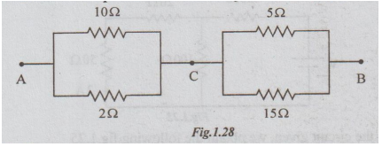
Solution: Step: 1

RP2 = 10 || 2
= 10 × 2/10 + 2 = 20/12
= 1.67Ω
Step: 2
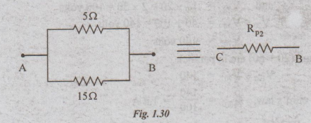
RP2 = 5||15 = 5×15/5 + 15 = 3.75Ω
Step 3: RP1 and RP2 are in series,
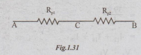
RAB = RAC + RCB =RP1+ RP2=1.67 +3.75
Ans: RAB = 5.42 Ω
Example 4 A circuit consisting of three resistances 12 Ω 18Ω and 36Ω respectively joined in parallel is connected in series with a fourth resistance. The whole circuit is applied with 60 V and it is found that the power dissipated in the 12Ω resistor is 36 W. Determine the value of the fourth resistance and the total power dissipated in the circuit.
Solution:
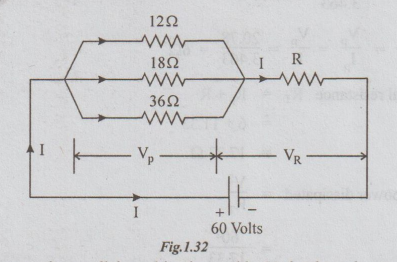
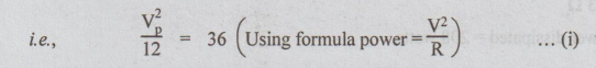
Let VP be the voltage across the parallel combination and let VR be the voltage across R.
Given that power dissipated in 12 Ω = 36 watts.
VP = √36 × 12 = 20.78 volts.
VR = 60-20.78
= 39.22 volts
For R, applying ohm's law,
Substituting IR in (iii),
R = 39.22 /3.463 = 11.33Ω
and RP = Vp/IP = VP/I = 20.78/3.463 = 6Ω
Total resistance RT = RP + R
= 6 + 11.33
= 17.33Ω
Total power dissipated = V2/RT
= 602/17.33
= 208 watts
Ans: (i) R = 11.33Ω
(ii) Total power dissipated = 208 watts
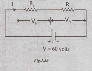
Example 5 Determine the value of R if the power dissipated in 10 ohm resistor is 40 W for the circuit shown.
Solution:

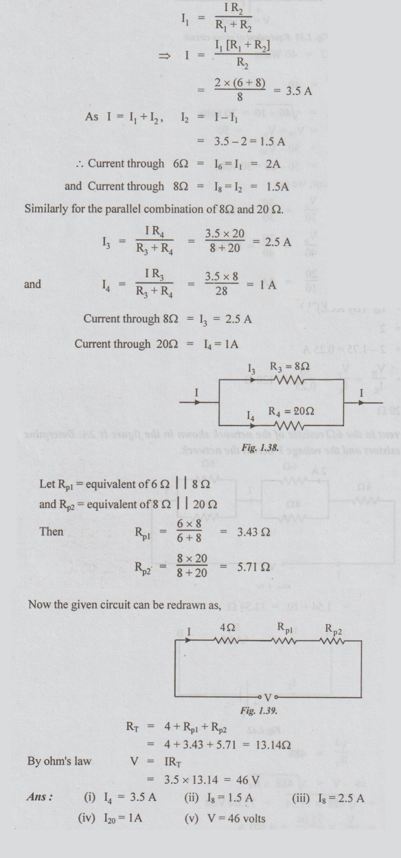
Example 6 The current in the 6Ω resistor of the network shown in the figure is 2A. Determine the currents in all other resistors and the voltage Vacross the network.
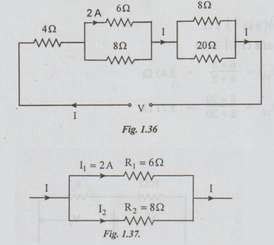
Solution:
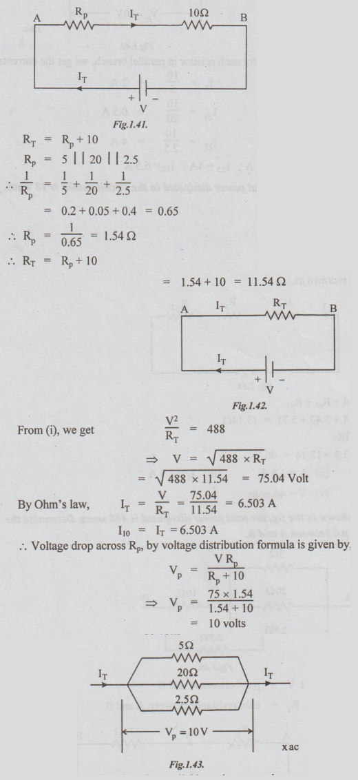
Example 7 In the circuit shown in the fig, the total power dissipated is 488 watts. Determine the current in each resistor and the p.d between A and B.
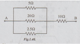
Solution:
Let V = p.d. between A and B
and RT = total resistance between A and B
By applying ohm's law for each resistor in parallel branch, we get the currents as follows:
I5 = 10/5 = 2A
I20 = 10/20 = 0.5A
I25 = 10/2.5 = 4A
Ans: 15 = 2A; I20 = 0.5 A; I25 = 4A; I10 = 6.5 A
Example 8 If the total power dissipated in the circuit shown is 18 watts, find the value of R and current through it.
Solution: The given circuit can be re-drawn as shown below, for better understanding
Example 9 Find the value of E which yields a power dissipation of 50W in R3 of the following circuit.
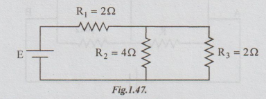
Solution: The original circuit can also be drawn as below:

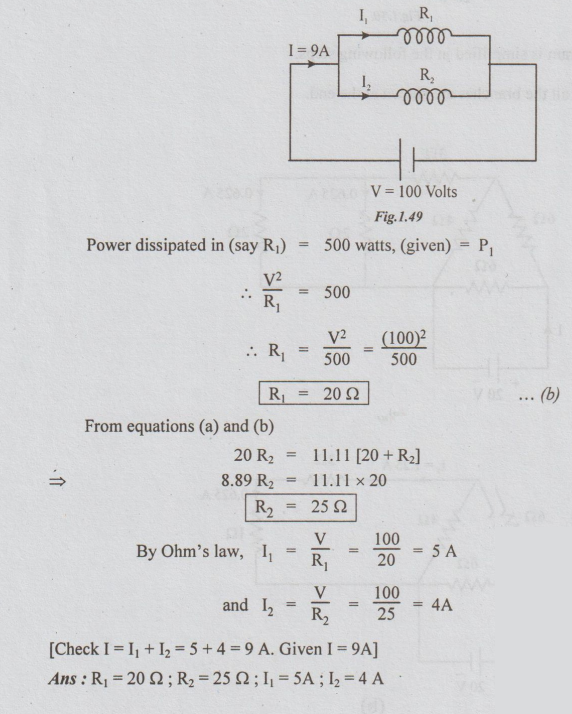
Example 10 Two coils connected in parallel across a 100 v.d.c. supply draw a total current of 9A. The power dissipated in one resistor is 500 watts. Find the resistance of two coils and current in each coil.
Solution: Data:
V =100 volts
I = 9A
P1 = 500 watts
R1 and R2 are in parallel.
RT = V/I = 100/9 = 11.11Ω ...(a)
R1 R2/R1+ R2 = 11.11
Example 11 Find the current supplied by the source in the circuit shown in the fig. Also determine the power in each resistor.
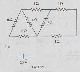
Solution: The circuit diagram is simplified in the following steps.
Note: The currents in all the branches are shown at the end.
Step 1:
Step 2:
Step 3:

Step 4:
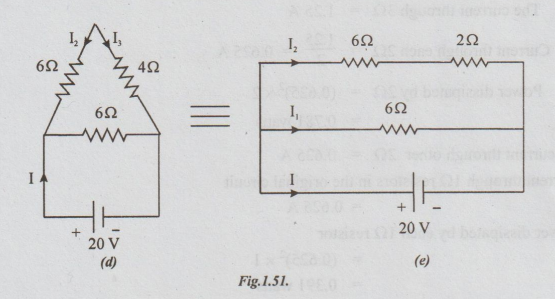
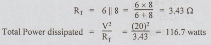
Step 5: Fig.1.53 (e), I1 = 20/6 = 3.33A
I2 = 20/8 = 2.5A
I = I1+I2
= 3.33+2.5
= 5.83A
Power dissipated in 6Ω = I12 × 6
= (3.33)2 × 6
= 66.53 watts
The power dissipated in another 6Ω resistor
= I22 × 6
=(2.5)2 × 6
= 37.5 watts
Represent I2 in figs 1.53 (d) and (c)
Refer fig (c), 4Ω and 4Ω are in parallel [equal-resistances]
I4 = I2/2 = 2.5.2
= 1/25A
Power dissipated in 4Ω = (1.25)2 × 4 = 6.25 W
Current through another 4Ω =1.25 A
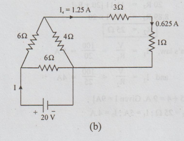
Transfer this current to the fig (b). Refer fig. (b).
Current through 3Ω = I4
Power dissipated by 3Ω= (1.25)2×3=4.6875 watts.
See the 30 in fig (a).
The current through 3Ω = 1.25A
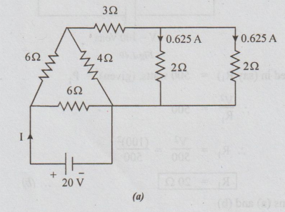
Current through each 2Ω = 1.25/2=0.625A
Power dissipated by 2Ω = (0.625)2 × 2 = 0.781 watts.
The current through other 2Ω = 0.625 A
Current through 1Ω resistors in the original circuit = 0.625A
Power dissipated by each 122 resistor
= (0.625)2 × 1= 0.391 watts
Answers as tabulation:
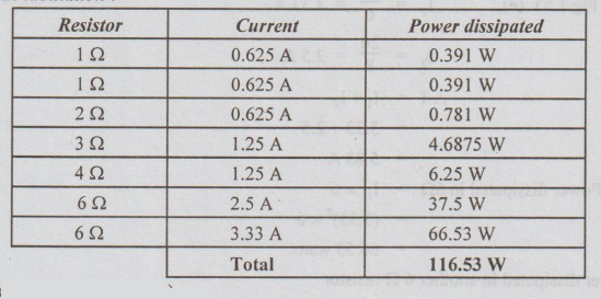
Note: For the circuit in fig. (e),
Check: Sum of power dissipated by all resistors = 116.53 watts
Example 12 Calculate the equivalent resistance of the following combination of resistors and also the source current.
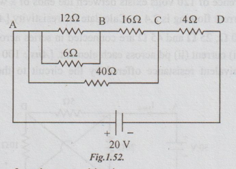
Solution: Start simplifying from inner combination.
Step 1: Replace parallel combination of 12 and 6Ω to get the following circuit.
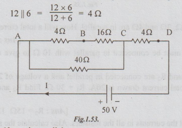
Step 2: (4+16) and 40 are in parallel.
Their equivalent resistance is =20 × 40/20 + 40 =13.3 Ω
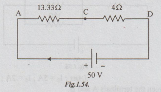
Step 3: 13.33 and 4 are in series.
RT = RAB = 13.33 +4
=17.33 Ω
Step 4: I = source current
= V/ RT = 50/17.33 = 2.885 A
Ans: (i) RT = 17.33Ω ; (ii) Source current I = 2.885 A
Electric Circuit Analysis: Unit I: b. Basic circuits analysis : Tag: : with Circuit Diagram, Equation, Solved Example Problems - Series-Parallel Circuits Combination of Resistors
Related Topics
Related Subjects

Electric Circuit Analysis
EE3251 2nd Semester 2021 Regulation | 2nd Semester EEE Dept 2021 Regulation