Electric Circuit Analysis: Unit V: Resonance and coupled circuits
Series resonance
ωo is not dependent on R. At resonance frequency, the inductive reactance = capacitive reactance i.e., the net reactance of the circuit at resonance is equal to zero.
SERIES RESONANCE
I
= E / Z ... (i)
At
resonance, the power factor being unity, Z = R.
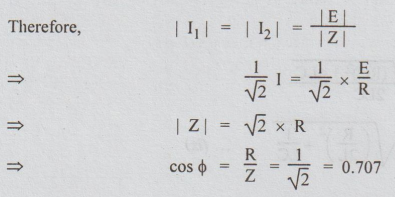
Therefore,
reactive part of the complex impedance must be zero i.e., (XL – XC)
= 0.
Equation
(ii) indicates that in a series RLC circuit resonance may be produced by (a)
varying frequency for a given L and C, (b) varying either L or C or both for
given frequency. So if frequency is varied, keeping
L
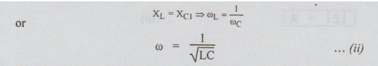
and C constant, the condition for resonance will be given by
ω
= 1/√LC
ωo
is called the angular resonance frequency in radian / sec.
Therefore,
the resonance frequency in
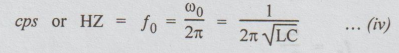
ωo
is not dependent on R. At resonance frequency, the inductive reactance =
capacitive reactance i.e., the net reactance of the circuit at resonance is
equal to zero.
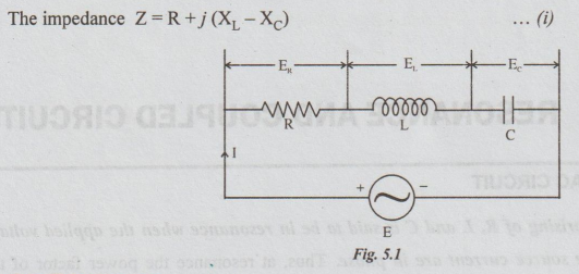
The
figure shows a series RLC circuit. E is the RMS value of the impressed voltage.
I
= the RMS value of the current.
ω
= angular frequency of supply in radians / sec
Series Resonance
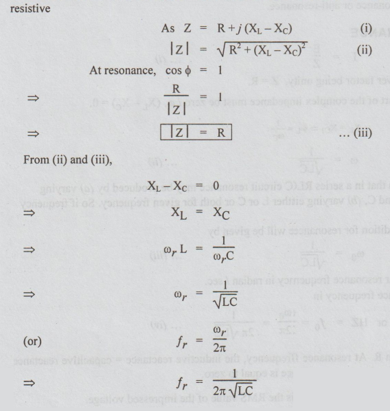
In
a R-L-C series circuit, when the current is in phase with the applied voltage,
the circuit is said to be in resonance. Then, phase angle is zero and hence
power factor is unity. The circuit acts as purely resistive
f,
or fo is called resonance frequency. At resonance, in a series circuit the
following main effects are to be observed.
(i)
Since XL = X C, the impedance is minimum and equal to
resistance i.e., Z r = R where Z r is impedance at
resonance.
(ii)
Since the impedance is minimum, the current is maximum.
The
current at resonance = It
=
V / Zr = V / R
(iii)
The power taken by the circuit is maximum because I, is maximum.
Power
taken by the circuit = Pt
=
Ir2 R
V2/R
(iv)
The voltage across L = VL = IXL
The
voltage across C = Vc = IXc
At
resonance, I = Ir, which is very large.
So,
VL and Vc are also very large.
(v)
In R-L-C circuit, at resonance both V and I are in phase. Hence, in the polar
form we can express them as V = |V| ∠0
and I= |I| ∠0.
In
otherwords, for R-L-C circuit if the applied voltage and source current are in
phase, the circuit is at resonance.
In
power systems, at resonance the excessive voltage built up across L and C
components (such as circuit breakers, reactors etc.) may cause damage. Hence,
in power systems, series resonance must be avoided.
But
the principle of series resonance is used to increase the signal voltage and
current at desired frequency, in some of the electronic circuits. Examples of
such electronic devices are antenna circuit of radio and T.V. receiver, tuning
circuits etc.
A
series resonant circuit has the capability to draw heavy currents and power
from the mains. So, it is often regarded as an acceptor circuit.
1. Phasor Diagram
Figure
5.2 shows phasor diagram for the series RLC circuit at three different
frequencies i.e., (i) f < fo, (ii) ffo, (iii) f > fo with L and C kept
constant.
For
any frequency lower than fo, XL < XC so, the circuit
behaves as a capacitive circuit. For any frequency, higher than fo, XL
> XC and the circuit behaves as an inductive one.
At
f=fo, XL = XC and hence current and source voltage are in
phase i.e., the circuit behaves as a resistive circuit.
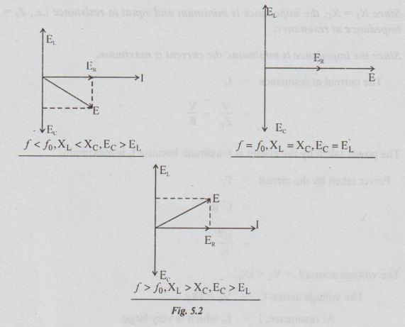
[Note:
1.
For a series combination E, and Ec are always in anti phase.
2.
At resonance EL = Ec. Voltmeter connected across L and that across C read same
magnitude. 3. If the voltmeter is connected across the series combination of L
and C, it reads zero at resonance.
4.
At resonance, in a series circuit, the impedance is minimum and hence current
maximum. In es to other words, if the current is maximum in a RLC series
circuit, we can definitely say that the circuit is in resonance. awon ni sonst
gemsbo
5.
At ffo, the power factor is unity (u.p.f). At f<fo, I leads E. So power
factor is leading in nature. For f > fo. I lags behind E. So the power
factor is lagging in nature.]
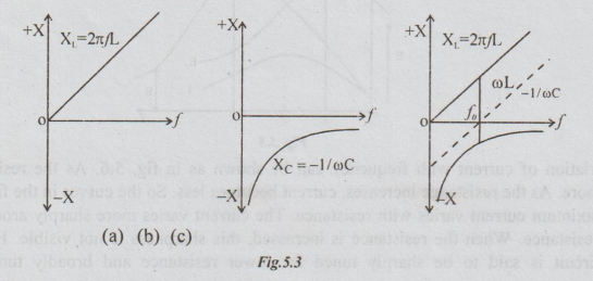
2. Reactance Curves
In
a series RLC circuit, three reactance curves can be plotted. Reactance curves
are the graphs between reactance and frequency. They are:
(a)
Inductive reactance (XL) versus frequency.
(b)
Capacitive reactance (XC) versus frequency.
(c)
Total reactance [X = (XL – XC)] versus frequency.
XL
= ωL=2лƒL. It shows linear variation.
Xc
= 1/ωC = 1/2πfC
It
shows a rectangular hyperbolic shape.
For
lesser frequency than fo, X is capacitive. At f = fo, X = 0. For f>fo, X is
inductive. The various reactance curves are shown in the following figures.
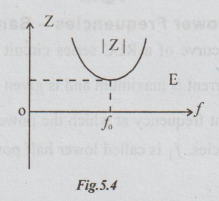
3. Variation of Impedance with Frequency for RLC Series Circuit
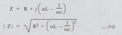
From
equation (vi), it is evident that at f = fo, | Z |= R. At all other frequencies
| Z❘ > R.
For
lesser frequency than fo, the impedance is capacitive and hence the power
factor is leading in nature. At frequencies above fo, the impedance is
inductive and hence the power factor is lagging in nature.
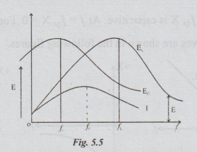
4. Variation of Current and Voltage Distribution in a Series RLC Circuit with Frequency
At
resonance frequency, Z is minimum and hence current is maximum. The variations
of EL and EC are also shown in fig.5.5. Neither EC
nor E, has the maximum value at resonance frequency. They are equal in
magnitude and opposite in phase at f0.
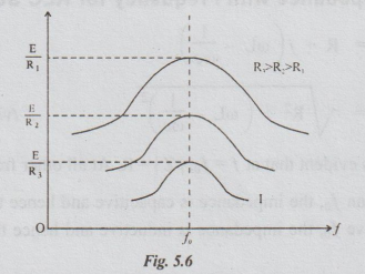
The
variation of current with frequency can be shown as in fig. 5.6. As the
resistance is less, current is more. As the resistance increases, current
becomes less. So the curves in the fig. 5.6 show as how the maximum current
varies with resistance. The current varies more sharply around fo for low
values of resistance. When the resistance is increased, this sharpness is not
visible. Hence, a series resonant circuit is said to be sharply tuned for lower
resistance and broadly tuned for higher resistance.
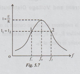
5. Selectivity-Q-Half Power Frequencies - Bandwidth
The
current versus frequency curve of a RLC series circuit is symmetrical about the
resonance frequency. At frequency fo, the current is maximum and is given by
E/R . There will be two frequencies f1, f2 on either side of the resonant
frequency at which the power is half the power at resonance. So, they are
called half power frequencies. f, is called lower half power frequency and f2
is called upper half power frequency.
Power
at points 1 and 2 = I12 R = I22 R.
Power at resonance = I2 R
By
definition of half-power frequencies,
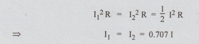
i.e.,
at half-power points 1 and 2, the current is 70.7% of the current at resonance.
Let
Z be the impedance at half-power points.
i.e.,
at half-power points, the power factor is 0.707 or = 45°. At f1, power factor
is leading in nature and at f2, it is lagging in nature.
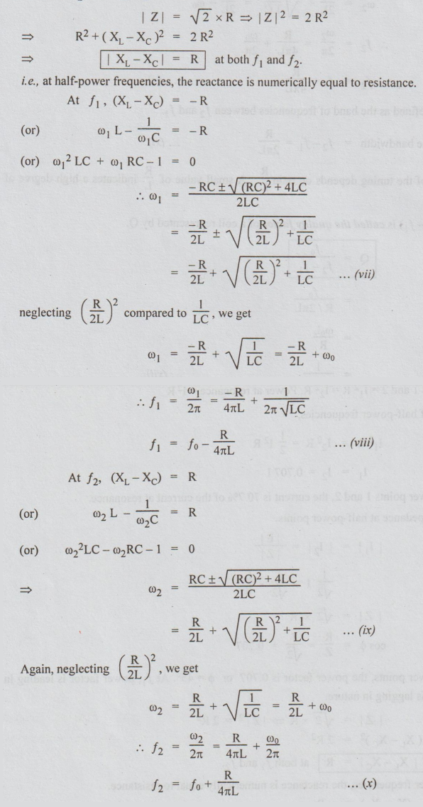
The
bandwidth is defined as the band of frequencies between f2 and f1.
The
bandwidth = f2 - f1 = R / 2πL … (xi)
The
sharpness of the tuning depends on ratio R/L A small value of R/L indicates a
high degree of sensitivity.
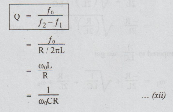
Ratio
fo to (f2-f1) is called the quality factor of a coil represented by Q.
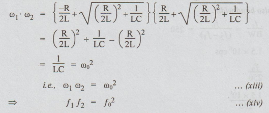
From the above equation, we can say that f1, fo, f2 are in Geometric progression.
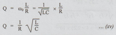
[Note:
Q can be expressed in terms of R, L and C as below.]
Electric Circuit Analysis: Unit V: Resonance and coupled circuits : Tag: : - Series resonance
Related Topics
Related Subjects

Electric Circuit Analysis
EE3251 2nd Semester 2021 Regulation | 2nd Semester EEE Dept 2021 Regulation