Electrical Machines II: UNIT V: a. Single Phase Induction Motors
Shaded Pole Induction Motors
Circuit, Characteristics, Phasor diagram, Operation Working Principle, Construction, Applications
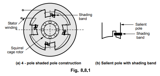
The poles are shaded i.e. each pole carries a copper band on one of its unequally divided part called shading band.
Shaded Pole Induction Motors
This
type of motor consists of a squirrel cage rotor and stator consisting of
salient poles i.e. projected poles. The poles are shaded i.e. each pole carries
a copper band on one of its unequally divided part called shading band.
Fig. 8.8.1 (a) shows 4 pole shaded pole construction while Fig. 8.8.1 (b) shows
a single pole consisting of copper shading band.
When
single phase a.c. supply is given to the stator provided to the poles, a rotating
magnetic field is generated, magnetic field can be explained as below :
The
current carried by the stator winding is alternating and produces alternating
flux. The waveform of the flux is shown in the Fig. 8.8.2 (a).
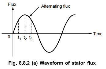
The
distribution of this flux in the pole area is greatly influenced by the role of
copper shading band. Consider the three instants say t1 t2
and t3 during first half cycle of the flux as shown, in the Fig-
8-8.2 (a)
At instant t = t1 rate of rise of current and hence the flux is very high. Due to the transformer action, large e.m.f. gets induced in the copper shading band. This circulates current through shading band as it is short circuited, producing its own flux. According to Lenz's law, the direction of this current is so as to oppose the cause i.e. rise in current. Hence shading ring flux is opposing to the main flux. Hence there is crowding of flux in nonshaded part while weakening of flux in shaded part. Overall magnetic axis shifts in nonshaded part as shown in the Fig. 8.8.2 (b)
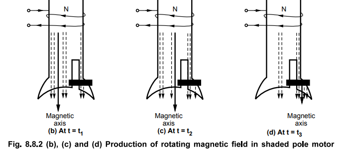
At
instant t – t2, rate of rise of current and hence the rate of change
of flux is almost
zero as flux almost reaches to its maximum value. So dϕ / dt = 0. Hence there is very little induced e.m.f. in the shading ring. Hence the shading ring flux is also negligible, hardly affecting the distribution of the main flux. Hence the main flux distribution is uniform and magnetic axis lies at the centre of the pole face as shown in the Fig. 8.8.2 (c).
At instant t – t3, the current and the flux is decreasing. The rate of decrease is high which again induces a very large e.m.f. in the shading ring. This circulates current through the ring which produces its own flux. Now direction of the flux produced by the shaded ring current is so as t oppose the cause which is decrease in flux. So it oppose the decrease in flux means its direction is same as o that of main flux, strengthening it. So there is crowding of flux in the shaded part as compared to nonshaded part. Due to this the magnetic axis shifts to the middle of the shaded part of the pole. This is Fig. shown in the Fig. 8.8.2 (d)
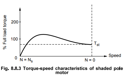
This
sequence keeps on repeating for negative half cycle too. Consequently this
produces an effect of rotating magnetic field, the direction of which is from
nonshaded part of the pole to the shaded part of the pole. Due to this, motor
produces the starting torque and starts rotating. The starting torque is low
which is abut 40 to 50 % of the full load torque for this type of motor. The
torque speed characteristics is shown in the Fig. 8.8.3.
Due
to absence of centrifugal switch the construction is simple and robust but this
type of motor has a lot of limitations as :
1.
The starting torque is poor.
2.
The power factor is very low.
3.
Due to I2R, copper losses in the shading ring the efficiency is very
low.
4.
The speed reversal is very difficult. To achieve the speed reversal, the
additional set of shading rings is required. By opening one set and closing
other, direction can be reversed but the method is complicated and expensive.
5.
The size and power rating of these motors is very small. These motors are
usually available in a range of 1/300 to 1/20 kW.
1. Applications
These
motors are cheap but have very low starting torque, low power factor and low
efficiency. These motors are commonly used for the small fans, toy motors,
advertising displays, film projectors, record players, gramophones, hair
dryers, photo copying machines etc.
Review Questions
1. Explain the principle of operation of shaded pole induction
motor along with the torque-slip
characteristics and the applications.
2. Explain the different method of starting the single phase
induction motor. Compare them. AU : May-07, 09, Dec.-09, Marks 16
Electrical Machines II: UNIT V: a. Single Phase Induction Motors : Tag: Engineering Electrical Machines - II : Circuit, Characteristics, Phasor diagram, Operation Working Principle, Construction, Applications - Shaded Pole Induction Motors
Related Topics
Related Subjects

Electrical Machines II
EE3405 Machine 2 EM 2 4th Semester EEE Dept | 2021 Regulation | 4th Semester EEE Dept 2021 Regulation