Linear Integrated Circuits: Unit III: Applications of Op-amp
Sine Wave Generators (Oscillators), Phase Shift Oscillator using Op-amp
Working Principle, Pulse, Circuit Diagram, Advantages, Disadvantage, Design, Solved Example Problems | Operational amplifier
The sine wave is certainly one of the most fundamental waveforms. A variety of circuits and techniques have been developed for the generation of sine waves. The conventional sine wave oscillator circuits use phase shifting techniques that usually employ.
Sine Wave Generators (Oscillators)
The
sine wave is certainly one of the most fundamental waveforms. A variety of
circuits and techniques have been developed for the generation of sine waves.
The conventional sine wave oscillator circuits use phase shifting techniques
that usually employ.
•
Two RC tuning networks, and
•
Complex amplitude limiting circuitry
Let
us discuss the two commonly used oscillators for the sine wave generation.
Phase Shift Oscillator
RC
phase shift oscillator basically consists of an amplifier and a feedback
network consisting of resistors and capacitors arranged in ladder fashion.
Hence such an oscillator is also called ladder type RC phase shift oscillator.
To
understand the operation of this oscillator let us study RC circuit first,
which is used in the feedback network of this oscillator. The Fig. 3.17.1 shows
the basic RC circuit.
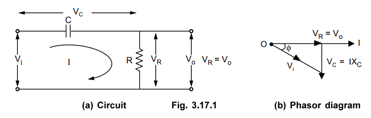
The
capacitor C and resistance R are in series. Now XC is the capacitive reactance in ohms given by,
XC
= (1 / 2πfC) Ω
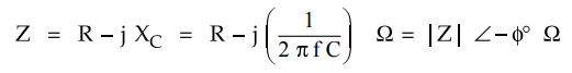
The
total impedance of the circuit is,
The
r.m.s. value of the input voltage applied is say V4 volts. Hence the current is
given by,
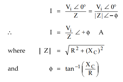
From
expression of current it can be seen that current I leads input voltage Vi
by angle ϕ. The output voltage Vo is the drop
across resistance R given by,
Vo
= VR = IR
The
voltage across the capacitor is,
VC
= I XC
The
drop VR is in phase with current I while the drop VC lags current I
by 90° i.e. I leads VC by 90°. The phasor diagram is shown in the
Fig. 3.17.1 (b).
Key
Point By using proper values of R and C, the angle 0
is adjusted in practice equal to 60°.
1. RC Feedback Network
As
stated earlier, RC network is network must introduce a phase shift of 1809 to
obtain total phase shift around a loop as 360°. Thus if one RC network produces
phase shift of 0 = 6(F then to produce phase shift of 1809 such three RC
networks must be connected in cascade. Hence in RC phase shift oscillator, the
feedback network consists of three RC sections each producing a phase shift of
60°, thus total phase shift due to feedback is 180° (3 × 60°) Such a feedback
network is shown in the Fig. 3.17.2.
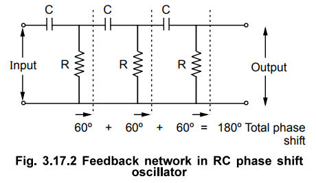
The
network is also called the ladder network. All the resistance values and all
the capacitance values are same, so that for a particular frequency, each
section of R and C produces a phase shift of 60°.
2. R-C Phase Shift Oscillator using Op-amp
R-C
phase shift oscillator using op-amp uses op-amp in inverting amplifier mode.
Thus it introduces the phase shift of 180” between input and output. The
feedback network consists of 3 RC sections each producing 60° phase shift. Such
a RC phase shift oscillator using op-amp is shown in the Fig. 3.17.3.
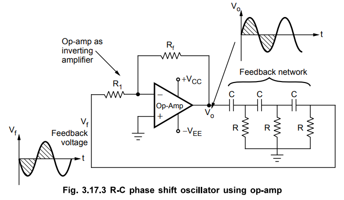
The
output of amplifier is given to feedback network. The output of feedback
network drives the amplifier. The total phase shift around a loop is 180° of
amplifier and 1809 due to 3 RC section, thus 360°. This satisfies the required
condition for positive feedback and circuit works as an oscillator.
3. Derivation of Frequency of Oscillations
Let
us find the transfer function of the RC feedback network.
Applying
KVL to various loops we get,
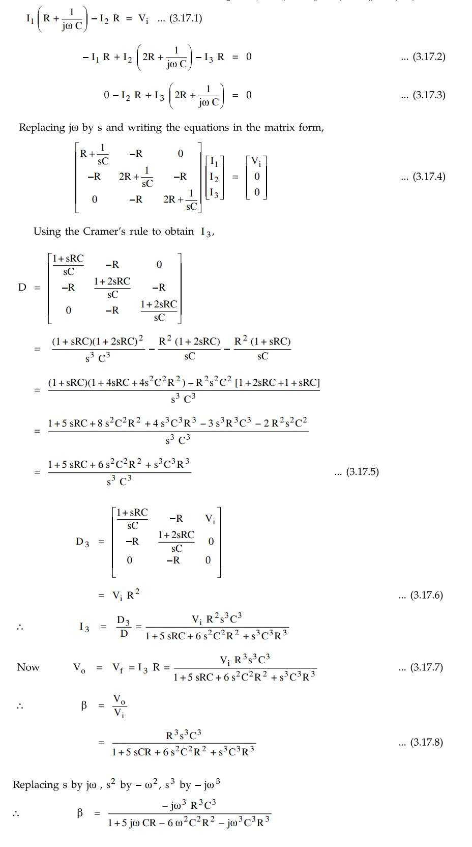
Dividing
numerator and denominator by –jω3 R3 C3 and
using,
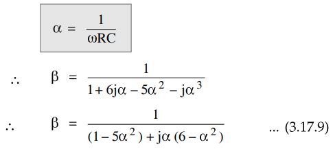
To
have phase shift of 180°, the imaginary part in the denominator must be zero, a
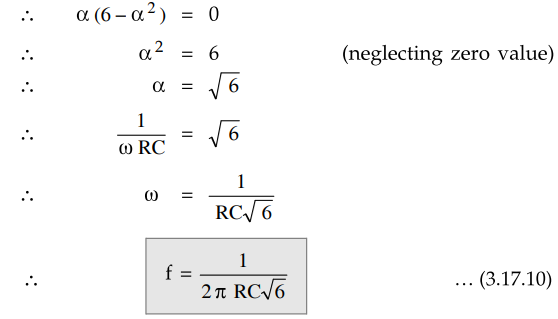
This
is the frequency with which circuit oscillates.
At
this frequency,
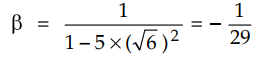
Negative
sign indicates phase shift of 180°
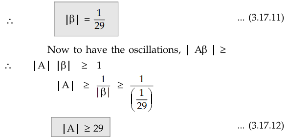
Key
Point For the oscillations to occur, the gain of the
op-amp must he equal to or greater than 29, which can be adjusted using the
resistances Rf and Ri.
4. Advantages
The
advantages of R-C phase shift oscillator are,
1.
The circuit is simple to design.
2.
Can produce output over audio frequency range.
3.
Produces sinusoidal output waveform.
4.
It is a fixed frequency oscillator.
5. Disadvantage
By
changing the values of R and C, the frequency of the oscillator can be changed.
But the values of R and C of all three sections must be changed simultaneously
to satisfy the oscillating conditions. But this is practically impossible.
Hence the phase shift oscillator is considered as a fixed frequency oscillator,
for all practical purposes.
And
the frequency stability is poor due to the changes in the values of various
components, due to effect of temperature, aging etc.
6. Phase Shift Oscillator Design
Practically
the resistance Rf of the inverting amplifier is designed, by making
current through it, much larger than input bias current of the op-amp.
Let
the current through Rf is I1 then
I1
= 100 Ib (max) … (3.17.13)
Without
amplitude stabilization, the output of the oscillator oscillates between the
levels ± Vsat.
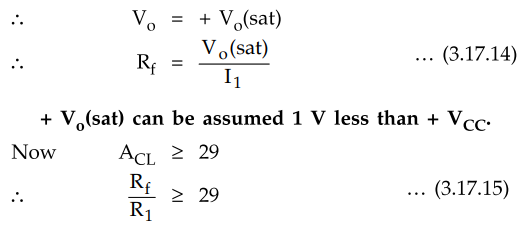
Design
the value of R1 from the gain requirement.
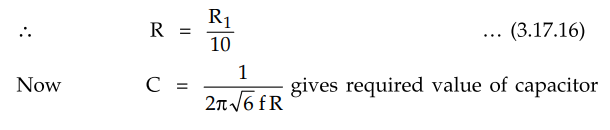
To
prevent the loading of the amplifier because of RC networks, it is necessary
that R1 ≥ 10 R.
Note
that for output frequency less than 1 kHz, op-amp 741 is used but for higher
frequencies LM 318 or LF 351 op-amps are recommended due to their higher slew
rates.
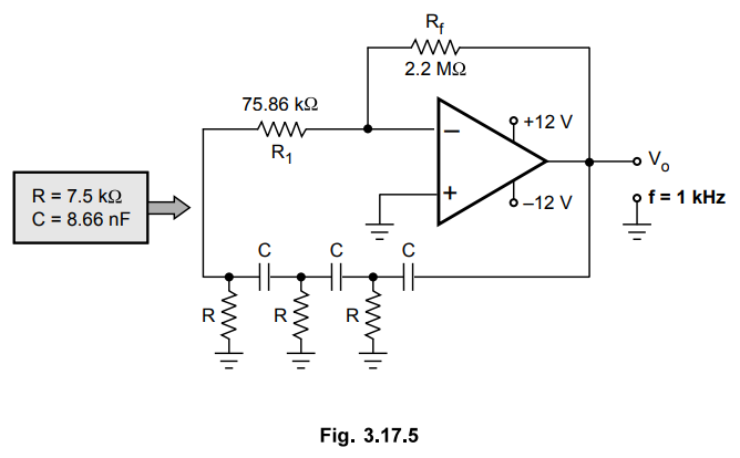
Example
3.17.1 Design a RC phase shift oscillator for a frequency
of 1 kHz.
Dec.-04,
14, Marks 8
Solution
:
Use op-amp 741 with Ib (max) = 50 nA

The
designed circuit is shown in the Fig. 3.17.5
Review Question
1. Draw the circuit of a RC phase shift oscillator using
operational amplifier and derive an expression for the condition of
oscillation, gain of op-amp and frequency of oscillation.
Dec.-04, 12, May-05, 12, Marks 16
Linear Integrated Circuits: Unit III: Applications of Op-amp : Tag: : Working Principle, Pulse, Circuit Diagram, Advantages, Disadvantage, Design, Solved Example Problems | Operational amplifier - Sine Wave Generators (Oscillators), Phase Shift Oscillator using Op-amp
Related Topics
Related Subjects

Linear Integrated Circuits
EE3402 Lic Operational Amplifiers 4th Semester EEE Dept | 2021 Regulation | 4th Semester EEE Dept 2021 Regulation