Electrical Machines II: UNIT V: b. Special Machines
Single Phase Commutator Motors
Construction, Working Principle, Torque-speed Characteristics, Advantages, Limitations
The commutator is a feature of d.c.motors. But a.c. motors having wound rotor with brushes and commutator arrangements, are called commutator motors which work on single phase a.c. supply.
Single Phase Commutator Motors AU
: May-03, 04, 08, 13, 16,17,18, Dec.-06, 10, 11, 13, 16
The
commutator is a feature of d.c.motors. But a.c. motors having wound rotor with
brushes and commutator arrangements, are called commutator motors which work on
single phase a.c. supply. The commutator arrangement present in these motors is
similar to the armature of a d.c. motor. In this section we will discuss two
types of single phase commutator motors namely a.c. series motors and the
universal motors which are widely used in practice.
1. Single Phase A.C. Series Motor
In
a normal d.c. motor if direction of both field and armature current is
reversed, the direction of torque remains unchanged. So when normal d.c.series
motor is connected to an a.c. supply, both field and armature current get
reversed and unidirectional torque gets produced in the motor hence motor can
work on a.c. supply.
But
performance of such motor is not satisfactory due to the following reasons :
i)
There are tremendous eddy current losses in the yoke and field cores, which
causes overheating.
ii)
Armature and field winding offer high reactance to a.c. due to which operating
power factor is very low.
iii)
The sparking at brushes is a major problem because of high voltage and current
induced in the short circuited armature coils during the commutation period.
Some
modifications are required to have the satisfactory performance of d.c.series
motor on a.c. supply, when it is called a.c. series motor. The
modifications are :
i)
To reduce the eddy current losses, yoke and pole core construction is
laminated.
ii)
The power factor can be improved by reducing the magnitudes of field and
armature reactances. Field reactance can be decreased by reducing the number of
turns. But this reduces the field flux. But this reduction in flux (N ∝ 1/ ϕ)
increases the speed and reducing the torque. To keep the torque same it is
necessary to increase the armature turns proportionately. This increases the
armature inductance.
Now
to compensate for increased armature flux which produces severe armature
reaction, it is necessary to use compensating winding. The flux produced by
this winding is opposite to that produced by armature and effectively
neutralizes the armature reaction.
If
such a compensating winding is connected in series with the armature as shown
in the Fig. 9.4.1 (a),

the
motor is said to be 'conductively compensated'. For motors to be operated on
a.c. and d.c. both, the compensation should be conductive. If compensating
winding is shortcircuited on itself as shown in the Fig. 9.4.1 (b),

the
motor is said to be 'inductively compensated'. In this compensating winding
acts as a secondary of transformer and armature as its primary. The ampere
turns produced by compensating winding neutralise the armature ampere turns.
To
reduce the induced e.m.f. due to transformer action in the armature coils while
commutation period, the following measures are taken :
i)
The flux per pole is reduced and number of poles are increased.
ii)
The frequency of supply used is reduced.
iii)
Preferrably single turn armature coils are used.
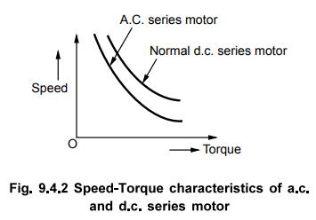
The
characteristics of such motor are similar to that of d.c. series motor. The
torque varies as square of the armature current and speed varies inversely as
the armature current. The speed of such motor can be dangerously high on no
load condition and hence it is always started with some load. Starting torque
produced is high which is 3 to 4 times the full load torque. The speed-torque
characteristics of such type of motor is as shown in the Fig. 9.4.2.
Applications
:
Because of high starting torque it is used in electric traction, hoists,
locomotives etc.
2. Universal Motor
There
are small capacity series motors which can be operated on d.c. supply or single
phase alternating supply of same voltage with similar characteristics, called
universal motors. The general construction of such motor is similar to that of
a.c. series motor as discussed in last article. It is manufactured in two
types.
i)
Non-compensated, low h.p.
ii)
Compensated type, high h.p.
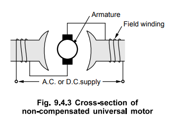
Non-compensated
type pole has 2 poles, having entire magnetic path as laminated.
Armature
is wound type similar to the normal d.c. motor. Such noncompensated
construction is shown in the Fig. 9.4.3.
While
in compensated type, the motor has distributed field winding consisting of main
field and compensating winding. This is somewhat similar to the stator of split
phase single phase induction motor type construction. This also has a wound
armature similar to the normal d.c. motor. Fig. 9.4.4 shows the connection
diagrams for both the types of universal motor.

Speed-Torque
characteristics : The speed - torque characteristics for
both the types of universal motor are shown in the Fig. 9.4.5.

Compensated
type universal motor has better speed-torque characteristics i.e. the characteristics
are same for the operation of motor on a.c. or d.c. supply. The motors are generally
designed for full load operating speeds ranging between 3000 to 20000 r.p.m.
Applications
:
Though compensated type characteristics are better, the non-compensated type
are more preferred for low h.p. applications. While compensated type of
universal motors are preferred for high h.p. applications. High starting torque
is the important feature of universal motors.
The
universal motors are used for domestic applications like vacuum cleaners, food
processors and mixers, hair driers, coffee grinders, electric shavers etc. Their
other applications are blowers, portable tools like drilling machines and small
drives.
3. Phasor Diagram of A.C. Series Motor
Consider
the equivalent circuit of a.c. series motor as shown in the Fig. 9.4.6.

It
is conductively coupled a.c. motor.
When
armature current Ia flows through it, there is voltage drop across each winding
impedance and induced e.m.f. Eb(a.c.), when a.c. supply is given to it
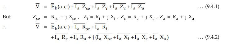
Thus
adding the drops Ia R and Ia X to Eb(a.c.) vectorially, the voltage V can be
obtained. As Eb(a.c.) is produced due to current Ia, it is proportional to Ia
and in phase with it. Thus the phasor diagram with Ia as reference is shown in
the Fig. 9.4.7. The angle between V and Ia is and cos is the power factor of
the motor.
Example
9.4.1 A universal motor has a resistance of 30 ohm and
an inductance of 0.5 H. When connected to a 250 volt d.c. supply and loaded to
0.8 amp, it runs at 2000 r.p.m. Determine the speed, torque and power factor
when connected to 250 volt, 50 Hz A.C. supply and loaded to take same amount of
current.
Solution
:
On
d.c. supply,
Eb(d.c.)
= V - Ia Ra = 250 - 0.8 × 30 = 226 V
Ndc
= 2000 r.p.m.
The
inductance does not play any role in d.c. operation.
On
a.c. supply,

The
phasor diagram is shown in the Fig. 9.4.8.

From
the phasor diagram, consider triangle OCD
(OC)2
= (OD) 2 + (CD) 2 = (OA + AD2 + (CD) 2

Review Questions
1. Write a brief note on a.c. series motor.
2. What modifications are necessary in a d.c. series motor so
that it may work satisfactorily on a.c. supply? Explain its operation. State
its applications.
3. Explain the construction and working of a.c.series motor.
Electrical Machines II: UNIT V: b. Special Machines : Tag: Engineering Electrical Machines - II : Construction, Working Principle, Torque-speed Characteristics, Advantages, Limitations - Single Phase Commutator Motors
Related Topics
Related Subjects

Electrical Machines II
EE3405 Machine 2 EM 2 4th Semester EEE Dept | 2021 Regulation | 4th Semester EEE Dept 2021 Regulation