Electrical Machines: Unit I: b. Electromechanical Energy Conversion
Singly Excited Magnetic System
The analysis of singly excited magnetic system includes the derivations of expressions of electrical input energy, magnetically stored field energy and the mechanical force.
Singly
Excited Magnetic System
AU : May-03, 04, 05, 06, 09, 10, 11, 14, 16, 19, Dec.-02, 04, 09, 10, 13, 14, 16, 17, 18, April-03
• The analysis of singly excited magnetic system includes the derivations of expressions of electrical input energy, magnetically stored field energy and the mechanical force. Consider attracted type electromechanical armature relay as a singly excited magnetic system. It is shown in the Fig. 2.6.1.

•
The following assumptions are made while performing the analysis of singly
excited magnetic system,
1.
The resistance of the exciting coil is assumed to be present in lumped form,
outside the coil. Thus coil is lossless and ideal.
2.
The leakage flux does not take part in energy conversion process so it is
neglected as practically it is small. Hence all the flux is confined to the
iron core and links all the N turns of coil.
Thus
if total flux is ϕ and turns of coil N then,
Flux
linkages = Nϕ Wb-turns ... (2.6.1).
3.
The leakage inductance is negligible.
4.
There is no energy loss in the magnetic core. The reluctance of the iron path
is neglected as negligible.
1. Electric Energy Input
•
Due to the flux linkages λ, the reaction e.m.f. e exists, whose direction is so
as to oppose the cause producing it i.e. voltage v according to Lenz's law as
shown in the Fig. 2.6.1 This e.m.f. is given by,
e=
dλ/dt .... (2.6.2)
•
Applying Kirchhoff's voltage law to the coil circuit,
v
= ir + e ...(2.6.3)
ஃ v = ir + dλ/dt ...(2.6.4)
Multiplying both sides by i,
Vi = i2 + dλ/dt i

•
Thus the magnetic system extracts the electric energy from the supply.
2. Magnetic Field Energy Stored
•
Consider that the armature is held fixed at position X. As armature is not
moving, the mechanical work done is zero. Hence according to energy balance
equation, the entire electric energy input gets stored in the magnetic field.
ஃ dWe
= dWf ... dWm = 0
Key Point :
This indicates that when moving part of any physical system is held fixed, then
the entire electrical energy input gets stored in the magnetic field.
ஃ dWf= ei dt =
i d λ = f dϕ ... (2.6.8)
•
The relationship i - λ or f - ϕ is basically nonlinear for a magnetic circuit,
similar to the B-H relationship. It shows hysteresis effect.
•
From equation (2.6.8), the energy absorbed for a finite change in flux linkage
can be obtained as,

•
If the initial flux and flux linkages are zero i.e. Φ1 = λ1
= 0 then the energy stored in the magnetic field to establish the flux ϕ is
given by,

•
This is the energy stored in the magnetic field when the flux ois established
in it.
Key Point :
When a magnetic circuit undergoes a cycle ϕ1 + ϕ2 = ϕ1,
it undergoes a cycle of magnetization and demagnetization. The hysteresis and
eddy current effects are dominant under such condition. Thus there is an irrecoverable
energy loss due to hysteresis and eddy currents.
• In our analysis it is assumed that these losses are separated out and supplied by the electric source used. Hence the coil is ideal lossless coil. Such a magnetic system is called conservative system.
• i - λ Relationship : The i - λ
relationship is similar to the magnetization curve for a magnetic material for
various values of x, the relationship is shown in the Fig. 2.6.2.

•
Practically λ may vary according to i or i may vary according to λ. So
mathematically this relationship is expressed as,
i
= i (λ, x) ... λ = Independent variable
a
= λ(i, x) ... i = Independent variable
• Depending upon the independent variable the stored
field energy is also the function of i, x or λ,
ஃ Wf
=Wf (λ,x) or Wf
Wf (i, x) ...(2.6.11)
Key Point :
If x is changed then energy interchange takes place in magnetic coupling field
and mechanical system. If x is held constant then energy interchange takes
place between electric system and magnetic coupling field.
Concept of co-energy :
When armature is held open then almost entire m.m.f. is required to drive the
flux through air gap and hence magnetic saturation may not occur. So i - λ or f
- ϕ relationship is linear in nature as shown in the Fig. 2.6.3.

This
are OACO is complementary area of the i – λ rectangle and is defined as
co-energy denoted as Wf

Key Point:
The co-energy has no physical significance but it is important in obtaining magnetic
forces.
•
For a linear relationship between i and a without magnetic saturation,
Area
OABO = Area OACO

The
self induction L of the coil is defined as magnetic flux linkages per ampere.

The
co-energy can be expressed for linear case as
•
From equation (2.6.16) it can be observed that field energy Weis function of
two independent variables λ and x.
ஃ Wf(λ,
x) = ½ λ2 /L(x) ... (2.6.18)
where
L(x) = Inductance as a function of x
•
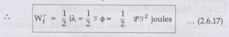
From equation (2.6.17) it can be observed that co-energy W’f is
function of two independent variables i and x.
ஃ W’f
(i, x) = ½ L(x) i2 ...
(2.6.19)
•
The equations (2.6.18) and (2.6.19) are general expressions for energy and
co-energy.
• Magnetic stored energy density :
The magnetic energy density is the magnetic stored energy per unit volume. It
is denoted as wf

Key Point : The
energy density expressions are important from the design point of view. The
density value indicates capability of material to store energy. Thus proper
dimensions so as to fully utilize the material, can be designed from energy
density values.
Magnetic stored energy interms of B
and H.
It
is known that magnetic stored energy is given by,

This
is magnetic stored energy.
i)
The iron path having length Ii and Magnectic field intensity H1
ii)
The air gap having length lg and magnectic field intensity Hg.
The
total ampere turns supplied to establish the flux through iron path and air gap
is Ni.
Ni
= Ampere turns for iron path + Ampere turns for air gap
Ni
= Hili + Hglg … (2.6.23)
λ
= N ϕ
= Total flux linkages … (2.6.24)

3. Mechanical Force
•
Consider that the magnetic field produces a mechanical force Ff as
shown in the relay. This force drives
the mechanical system consisting active and passive mechanical elements.
•
Let the armature moves a distance dx in positive direction i.e. in the
direction of force. The mechanical work done by the magnetic field then can be
obtained as,
dWm
= Ff dx ...(2.6.29)
•
As per the energy balance equation for electrical input,

• In such electromechanical systems the independent variables can be (i, x) or (λ, x).
Case
1 : The independent variables are (i, x) i.e. current constant
Thus
λ changes as i and x hence

•
As there is no term of di on left hand side of the equation, it should be zero
on the right hand side as well.

•
This is the expression for the mechanical force developed by the magnetic
coupling field
• Rearranging the terms, the equation can be written as,

• Now iλ is total area of i - λ relationship while we is the energy stored in the field, as shown in the Fig. 2.6.4.

Key
Point : This is the expression for system in which i is
independent variable. This means input current constant. Such a system is current
excited system.
Case 2 :
The independent variables are (λ, x) i.e. a is constant.
Thus
i changes as a and x hence,
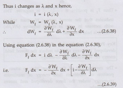
•
There are no terms of dà on the left hand side of the equation, the
corresponding term on the right hand side must be zero

Key Point :
This is the expression for system in which à is independent variable i.e. flux
producing voltage is constant. Such a system is voltage controlled system.
Thus
use equation (2.6.37) for current excited system while equation
(2.6.40) for voltage controlled system to find the mechanical force
developed.
Rotational system :
In rotational system, force is replaced by torque while linear displacement dx
is replaced by angular displacement dθ.

•
These are the expressions for the torque produced in rotational
systems.
•
Direction of mechanical force : Let us find out the
direction of the mechanical force developed. It is known that,
Ff
= - Wf(λ,x)/ ∂x
• Thus Ff is positive if ∂Wf(λ,x)/
∂x
is negative. This indicates that the stored energy Wf must reduce
with increase in x so as obtain negative (∂wf/∂x) when ∂ is held
constant.
Key Point :
Thus direction of the mechanical force developed is always so as to reduce the
stored field energy i.e. to increase the co-energy.
•
The moving part of the system tries to attain a position of minimum field
energy or maximum co-energy under the force developed and moves accordingly.
4. Determining Mechanical Force
• Let us determine the mechanical force for
non-linear and linear systems.
Case 1:
Non-linear
•
In non-linear case, the derivatives must be obtained numerically or graphically
by assuming small increment ∆x in x.
• Hence force can be expressed as,

Case 2 : Linear
From equation (2.6.19) it is known that,
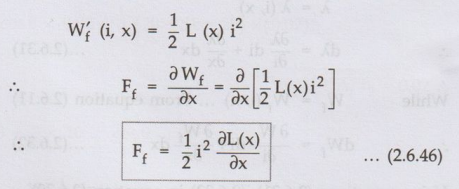
The
direction of force is so as to increase x. This reduces the reluctance of the
magnetic circuit.
The
inductance depends on reluctance given by,
ஃ
L= N2/S where S= Reluctance
So
as reluctance decreases, inductance increases.
Key Point :
Thus force Ff acts in the direction so as to increase inductance of
the coil.
Similarly
from equation (2.6.18) it is known that,

•
These are the various expressions for the mechanical force developed in singly
excited system.
•
Thus following observation can be made about direction of mechanical force or
torque developed in any physical system :
The direction is so as,
1.
Decrease the magnetic stored energy at constant λ.
2.
Increase the stored energy and co-energy at constant i.
3.
Decrease the reluctance.
4.
Increase the inductance.
5. Mechanical Energy
• Consider that the armature of the system has changed its position from x1 to x2 as shown in the Fig. 2.6.5.

Case 1 : Coil current constant
The
current in the coil is constant say in i0
The flux linking changes from ϕ1,
to ϕ2,
hence the flux linkages change from λ1, and λ2
Then the mechanical energy output is given by,

• For non-linear case, the corresponding i – λ relationship is as shown in the Fig. 2.6.6 (a).
• For the linear
case, i - λ relationship is shown in the Fig. 2.6.6 (b). From this it can be
written that,


•
This shows that half of the input electrical energy stored in the field while
half is converted to mechanical output energy.
Key Point :
Note that for this operation, the movement of armature from x1 to x2
must be very slow to keep coil current i0 constant.
Case 2 : The flux linkages constant
The
flux linkages with the coil are constant say λ0.
The
current changes from i1, to i2 .
It
is known that for 2 to be independent variable, a is constant hence
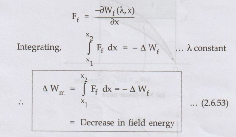
The
negative sign indicates that there is decrease in the stored field energy.
For
non-linear case, the corresponding i - λ relationship is shown in the
Fig. 2.6.7 (a).
For
the linear case, i – λ relationship is shown in the Fig. 2.6.7 (b) From
this it can be written that,

•
In both the linear and non-linear case, when a is constant, the change in input
electrical energy is zero as the voltage is maintained constant.
ஃ ∆We = 0 ... (2.6.55)
Key Point :
For achieving this, the armature must move from position 1 to position 2 very
quickly.
•
As input energy is zero, the part of field energy stored is used to do the
mechanical work. And thus stored energy decreases by same amount as equal to
change in mechanical energy output.
• Practical case :
Practically armature cannot move infinitely slow or it cannot move very fast
instantaneously. So neither current can remain constant nor λ remains constant
practically when armature moves from X1 to X2, the
current decreases from i1 to i2, while flux linkages λ
increases from λ1 to λ2 .
• The i-λ relationship for non-linear case is
shown in the Fig. 2.6.8 (a) while for linear case it is shown in the Fig. 2.6.8
(b).
 Key Point :
Practically this area must be calculated numerically or graphically.
Key Point :
Practically this area must be calculated numerically or graphically.
Ex. 2.6.1
The magnetic flux density on the surface
of an iron face is 1.8 T which is a typical saturation level value for
ferromagnetic material. Find the force density on the iron face. AU : April-03, May-11, Marks 8
Sol. :

Negative sign shows that force direction is so as to reduce x as it is force of attraction

Ex. 2.6.2 The λ
-i characteristics of singly excited electromagnet is given by I =121λ2x2
for 0 <i < 4 A and 0 < x < 10 cm. If the air gap is 5 cm and a
current of 3 A is flowing in the coil, calculate
i) Field energy ii) Co-energy iii) Mechanical
force on the moving part.
AU : May-06, Marks 8
Sol. :

Ex. 2.6.3 In a rectangular electromagnetic
relay, the exciting coil has 1500 turns of resistance 1 Ω. The cross-sectional
area of the core A = 5 cm × 5 cm. Neglect the reluctance of magnetic circuit
and fringing effects. If the coil is excited with an a.c. voltage of 50 Hz
frequency, having peak to peak value of 100 V and the armature is held at a
fixed distance of 1 cm, find the average force on the armature.
Sol. : The reluctance of magnetic circuit is to be neglected.

Ex. 2.6.4 The magnetic system shown in Fig.
2.6.9 has the following parameters : N = 500, i = 2A, Width of the air gap =
2.0 cm Depth of air gap = 2.0 cm, Length of air gap = 1 mm Neglect the
reluctance of the core, the leakage flux and the fringing flux.
i) Determine the force of
attraction between both sides of the air gap.
ii) Determine the energy stored in the air
gap.AU : Dec.-18,
Marks 13

Sol. : i)
The stored energy density is given by,

Ex. 2.6.5
Sketch L(x) and calculate the induced emf
in the excitation coil for a linear actuator shown in Fig. 2.6.10 (a) and (b). AU : Dec.-10, May-19, Marks 8
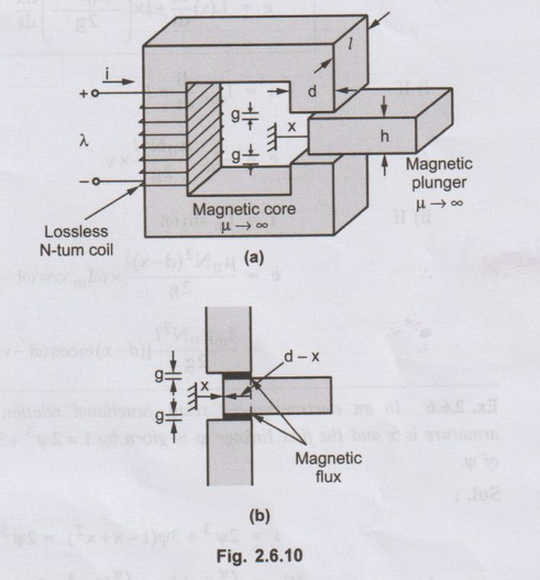
Sol.
:
The cross-sectional area of air gap is,

Ex. 2.6.6 In an electromagnetic relay, functional relation between the current i in the excitation coil, the position of armature is x and the flux linkage ψ is given by i = 2ψ3 +3ψ(1- x+x2), x > 0.5. Find force on the armature as a function of ψ.U : Dec.-15, Marks 8
Sol. :

Ex. 2.6.7
The electromagnetic relay shown in Fig.
2.6.11 is excited from a voltage source of v =
•√2 V sin wt. Assuming the reluctance of the magnetic circuit to be
constant, find the expression for the average force on the armature, when the
armature is held fixed at distance x. AU
: Dec.-17, Marks 13

Sol. :


Review Questions
1. Derive an
expression for co-energy density of an electromechanical energy conversion
device. AU
: Dec.-02,13, Marks 8
2. Explain about energy stored in magnetic system. AU : Dec.-16, May-03, Marks 8
3. Derive expression for mechanical force
developed by magnetic field. AU :
May-04,10, Dec.-14,16,17, Marks 8
4. Explain the i
- λ characteristic of a magnetic system.
Also derive expression for co-energy density assume the i-λ relationship of the
magnetic circuit is linear. AU : Dec.-04, Marks 16
5. Consider at
attracted armature relay is excited by an electric. Explain about the
mechanical force developed and the mechanical energy output with necessary
equations. For linear and non-linear cases. AU : May-14, 16. Dec.-04, Marks 10
6. Explain the
concept of singly excited machines and derive the expression for the
electromagnetic torque.AU : May-05, 19, Marks 8
7. Give the relation between field energy and the mechanical force
developed in the field. AU : May-09,
Marks 8
8. Discuss about
field energy and coenergy in magnetic system.AU : May-11, Marks 4
9. In a rectangular electromagnetic relay excited from a voltage source, the current and the flux linkages are related as i = λ [λ +2(1-x)2 ] where x < 1. Find the force on the armature as a function of λ.
(Ans. : 2λ2(1
– x))
Electrical Machines: Unit I: b. Electromechanical Energy Conversion : Tag: : - Singly Excited Magnetic System
Related Topics
Related Subjects

Electrical Machines I
EE3303 EM 1 3rd Semester EEE Dept | 2021 Regulation | 3rd Semester EEE Dept 2021 Regulation