Electron Devices and Circuits: Unit III: (b) MOSFET Amplifier
Small Signal Parameters of MOSFET
• The time-varying signal source in Fig. 7.1.1 (a) generates a time-varying component of the gate-to-source voltage.
Small Signal Parameters
•
The time-varying signal source in Fig. 7.1.1 (a) generates a time-varying
component of the gate-to-source voltage.
•
The instantaneous gate-to-source voltage is given by,
VGS
= VGSQ + Vi = VGSQ + Vgs (7.2.1)
Where
VGSQ is the d.c. component and VgS is the a.c. component.
•
The instantaneous drain current is,
ID
= K(VGS - VT)2 ...(7.2.2)
•
Substituting equation (7.2.1) into equation (7.2.2) we have,

•
The first term in equation (7.2.3(b)) represents the d.c. or quiescent drain
current Ipo, the second term represents the time-varying drain current
component that is linearly related to the signal vgs, and the third term is
proportional to the square of the signal voltage.
•
For a sinusoidal input signal, the squared term produces undesirable harmonics,
or nonlinear distortion, in the output voltage. To minimize these harmonics, we
must have
Vgs
<< 2 (VGSQ - VT) ...(7.2.4)
•
Which means that the third term in equation (7.2.3(b)) should be much smaller
than the second term. • Equation (7.2.4) represents the small signal condition
that must be satisfied for linear amplifiers.
•
Neglecting the vas term, we can write equation (7.2.3(b)) as
iD
= IDQ + id
where,
IDQ
== K(VGSQ - VT)2 … d.c. component and
id
= 2K (VGSQ - VT) Vgs … a.c. components
•
The small signal drain current is
related to the small signal gate-to-source voltage by the transconductance gm.
The relationship is given by,
gm
= Id / Vgs = 2K (VGSQ - VT) ...(7.2.6)
•
The transconductance can also be obtained from the derivative,
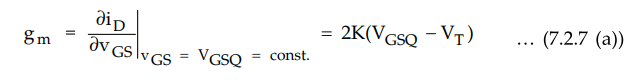
which
can be written

•
The transconductance is a ratio of output current to input voltage and hence it
represents the gain of the MOSFET.
•
The Fig. 7.2.1 shows the drain current versus gate-to-source voltage
characteristics for the MOSFET biased in the saturation region.
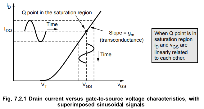
•
The transconductance gm is the slope of the curve.
•
If the time-varying signal Vgs is sufficiently small, the transconductance g is
a constant.
•
With the Q-point in the saturation region, the MOSFET operates as a current
source that is linearly controlled by VgS.
•
If the Q-point moves into the nonsaturation region, the MOSFET no longer
operates as a linearly controlled current source.
•
As shown in equation 7.2.7 (a), the transconductance
is directly proportional to the conduction parameter K, which in turn is a
function of the width-to-length ratio. Therefore, increasing the width of the
MOSFET increases the transconductance, or gain, of the MOSFET.
Ex.
7.2.1 Calculate the transconductance of a MOSFET having following parameters : VT = IV, 1/2µnCox =
30 µA/V2 and W/L = 50. Assume the drain current, ID = 1.2 mA.
Sol.:
K
= (1/2µnCox ) (W/L)
=
30 × 50 µA/V2 = 1.5 mA/ V2
Assuming
MOSFET is biased in the saturation region we have,
gm
= 2 √K IDQ = 2√(1.5) (1.2)
=
2.68 mA/V
Important
Concept
The
transconductance of a bipolar transistor is given by gm = ICQ/VT For
IDQ = 1.2 mA, the gm = 1.2 mA/0.026 V = 46.15 mAJV, which is quite
higher in comparison with the transconductance value of MOSFET. In general,
transconductance of MOSFET and hence the gain are smaller compared to those of
BJTs. This is the disadvantage of MOSFETs over BJTs.
Review Question
1. Explain the small signal parameters of MOSFET.
Electron Devices and Circuits: Unit III: (b) MOSFET Amplifier : Tag: : - Small Signal Parameters of MOSFET
Related Topics
Related Subjects

Electron Devices and Circuits
EC3301 3rd Semester EEE Dept | 2021 Regulation | 3rd Semester EEE Dept 2021 Regulation