Electrical Machines II: UNIT III: a. Three Phase Induction Motor
Special Rotor Constructions
Three Phase Induction Motor
This is the major advantage of slip ring induction motor that it gives high rotor resistance at starting and low rotor resistance at normal operating speed.
Special Rotor Constructions
In
case of slip ring induction motor an external resistance can be added in the
rotor circuit during starting which gives higher starting torque and lower
starting line current at an improved power factor. This resistance is then
gradually cut from the rotor circuit which would otherwise result in decrease
of full load speed, poor speed regulation, more rotor losses and hence reduced
efficiency. With lower rotor resistance it gives constant speed, low slip, less
losses and high efficiency. This is the major advantage of slip ring induction
motor that it gives high rotor resistance at starting and low rotor resistance
at normal operating speed.
In
case of squirrel cage induction motor there is no provision made for adding
external resistance. If the resistance is designed in such a way that it gives
better running performance then it has high starting current and consequently
low starting torque. This is major disadvantage of squirrel cage induction
motor although it is having the other qualities of low cost, ruggedness and
maintainance free operation. Thus the designers had found different ways of
improving the starting performance of the motor without affecting the running
performance of the motor.
In
squirrel cage induction motor high starting torque can be obtained by the use
of deep bar or double cage rotors. Both these types of rotors make use of skin
effect in which distribution of current is not uniform but the alternating
current has the tendency to concentrate near the surface of the conductor. Due
to this effect, effective area of cross section of the conductor is reduced and
hence resistance of the conductor is increased when carrying alternating
current.
The
solid conductor can be considered to be made up of large number of strands each
carrying a small part of current. The inductance of each strand will vary
according to the position. The strands in proximity of the centre are
surrounded by greater magnetic flux and has greater inductance than near the
surface. Due to high reactance at the centre, the alternating current flows
near the surface of the conductor. The skin effect depends upon nature of
material, diameter of wire, shape of wire and frequency.
Thus
the current in the rotor during starting is having the frequency of supply.
While under running condition the frequency of rotor current reduces to slip
frequency. This variation in frequency changes the rotor resistance as it
depends on skin effect. During starting it gives high resistance whereas it
gives low resistance during running condition which is desirable. Thus the
variation in rotor resistance can be achieved by deep bar or double cage
construction of rotor of induction motor. Both these types of constructions make
use of skin effect phenomenon.
1. Deep Bar Rotor Construction
There
is no constructional difference between stator of deep bar motor and that of
ordinary induction motor. The rotor consists of deep bars, short circuited by
two end rings one on each side. The deep and narrow rotor bar of rectangular
cross section is shown in the Fig. 5.22.1 (a). The other rotor bar shapes are
shown in the Fig. 5.22.1 (b). The magnetic leakage flux lines are shown by
dotted lines, Now consider that the bar consists of many number of layers of
different depths. The top and bottom layers are shown in the Fig. 5.22.1.

The leakage inductance of the bottom strip is greater than that of top strip as more flux links with bottom strip compared to top strip. All the strips are in parallel electrically. The bottom strip has greater leakage inductance than the top strip. During starting the rotor frequency is equal to the stator frequency and hence leakage reactance of bottom strip is largest and current in it is least. The top strip has low leakage reactance and current in it is large. Thus the current in low reactance top strip will be greater than that in high reactance lower strip and the current will be forced towards the top of the slot and phase of current in upper strip will lead that of the current in lower one. Thus there is non-uniform distribution of current which is shown in the Fig. 5.22.1. Due to this non-uniform distribution of current, and due to skin effect, effective area of cross section decreases. Hence rotor resistance increases resulting in high starting torque.
As
leakage reactance is proportional to frequency, the non-uniform distribution of
current depends upon the rotor frequency. The Fig. 5.22.2 shows a curve
indicating a.c. effective resistance to d.c. resistance with change in
frequency for a copper bar of 2.5 cm deep. The skin effect is maximum when
rotor is at standstill.

With
the increase in rotor speed, the rotor frequency decreases and skin effect also
decreases. The reactances of different strips at this low frequency become
almost equal and the current density over the conductor cross section becomes
uniform so its a.c. resistance is equal to d.c. resistance. Thus with deep bar
rotor has a low starting current with high starting torque without affecting
running performance of motor. The net reactance of deep bar rotor at standstill
is higher than that in a normal bar design, the breakdown or pull out torque in
deep bar rotor is lower. The torque-slip characteristics of deep bar motor and
normal induction motor is shown in the Fig.22.3.

The
equivalent circuit of induction motor is applicable to deep bar rotor also
wherein proper value of r2 and x2 must be determined for
satisfactory running performance. During starting their values should
correspond to effective value at stator frequency. During running their values
should correspond to their effective values at low rotor frequency.
2. Double Cage Rotor Construction
This
is another way of obtaining improved starting performance without affecting its
running performance. Though it is more expensive it gives better performance
than deep bar rotor construction.
The
stator of double cage rotor induction motor is same as that of ordinary
induction motor whereas its rotor consists of two cages or two layers of bars
short circuited by end rings since the upper cage is having smaller
cross-sectional area than the lower cage, the upper cage is having higher
resistance than that of lower cage. With equal cross-sectional areas of two
cages the upper cage is made up of high resistance material like brass,
aluminium, bronze etc. and the lower cage is made up of low resistance material
like copper. The upper cage and lower cage are separated by a narrow slit or
constriction. This is shown in the Fig. 5.22.4.

The
slot leakage flux pattern is also shown in the Fig. 5.22.4 for the double cage
rotor. Similar to deep bar rotor construction the rotor bars in the upper cage
have less leakage flux linkage and therefore has lower reactance. The dimension
of air construction controls the self leakage flux linking upper and lower
bars. If air constriction would have been absent then the main flux would
return via iron path between the two slots and thereby missing the bars in the
lower cages which will not contribute to production of torque in that case.
Hence it can be seen that the upper cage has high resistance and low reactance
whereas the lower cage has low resistance and high reactance.
During
starting the rotor frequency is same as stator frequency or supply frequency.
The division of rotor current in upper and lower cage is inversely proportional
to their leakage impedances. At the time of starting the leakage reactance of
lower cage is very high and consequently its leakage impedance is several times
greater than that of upper cage whose leakage reactance is small. Hence most
rotor current flows in upper cage having lower leakage impedance. The upper
cage having high resistance sharing the rotor current results in low starting
current at improved power factor giving high starting torque.
When
rotor speeds up, the rotor frequency decreases which decreases the leakage
reactance of lower cage. At normal operating speed the reactance difference
between the two cages is negligibly small. Hence the division of rotor current
in this case is mainly decided by the resistances of the two cages. As
resistance of upper cage is very high most of the current flows through the
lower cage giving excellent operating characteristics under running condition.
It can be noted that starting current is confined mainly with upper cage so if
there is frequent starting of motor then it would cause overheating and buring of upper cage.
The
torque-slip of double cage induction motor are shown in the Fig. 5.22.5.

Another
type of double cage rotor construction is also possible which is shown in the
Fig. 5.22.6. The slot-leakage flux pattern for this type of construction is
also shown.

The
approximate equivalent circuit of double cage rotor induction motor is shown in
the Fig. 5.22.7.

Though
the two cages are somewhat coupled magnetically, they can be treated as
independent for simplicity and it gives approximately same results. The two
cages are assumed to be parallel while drawing the equivalent circuit.
I2ru
and I'2rl are the currents in the upper and lower cages respectively
referred to the stator R2u and R2e are the resistances of
upper and lower cages referred to the stator whereas X2u and X2e
are the leakage reactances of the two cages referred to the stator of the
motor.
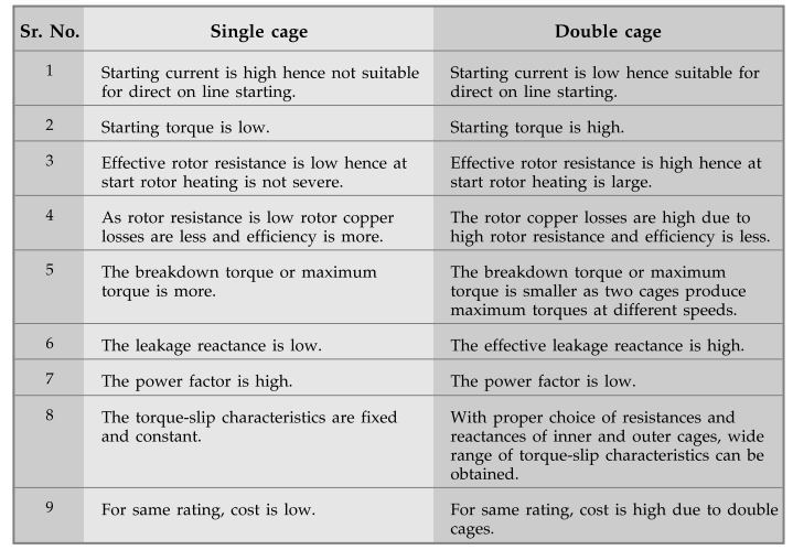
3. Comparison of Single Cage and Double Cage Motors
Single
cage
1.
Starting current is high hence not suitable for direct on line starting.
2.
Starting torque is low.
3.
Effective rotor resistance is low hence at start rotor heating is not severe.
4.
As rotor resistance is low rotor copper losses are less and efficiency is more.
5.
The breakdown torque or maximum torque is more.
6.
The leakage reactance is low.
7.
The power factor is high.
8.
The torque-slip characteristics are fixed and constant.
9.
For same rating, cost is low.
Double
cage
1.
Starting current is low hence suitable for direct on line starting.
2.
Starting torque is high.
3.
Effective rotor resistance is high hence at start rotor heating is large.
4.
The rotor copper losses are high due to high rotor resistance and efficiency is
less.
5.
The breakdown torque or maximum torque is smaller as two cages produce maximum
torques at different speeds.
6.
The effective leakage reactance is high.
7.
The power factor is low.
8.
With proper choice of resistances and reactances of inner and outer cages, wide
range of torque-slip characteristics can be obtained.
9.
For same rating, cost is high due to double cages.
Example
5.22.1
The outer and inner cages of a double cage induction motor have standstill impendances of (0.05 + j 0.10) Ω and (0.01 + j 0.6) Ω respectively. Find the ratio of the torques due to the two ages i) at starting ii) when running with 3% slip. Neglect stator impendance.
Solution
:
Zouter cage = (0.05 + j 0.10) Ω, Zinner
cage = (0.01 + j 0.60) Ω
R2o
= 0*05 Ω , X2o = 0.1 Ω
R2i
= 0.01 Ω, X2i = 0.6 Ω
Slip,
s = 3 % = 0.03
We
have to find the ratio of Touter cage and Touter cage at
standstill.
The
torque of induction motor is given by,

Example
5.22.2 The cages of a double cage IM have standstill
impedances of (3.5 +jl.5) Ω and (0.6 + j 7) Ω. Full load slip is 6 %. Find the
starting torque in terms of full load torque. Neglect stator impedance and
magnetizing current.
Solution
:
The equivalent circuit of induction motor by neglecting stator impedance and
magnetizing current can be represented as,

Impedance
of inner cage during starting is given as,
At
starting, s = 1
Zi
= Ri + j Xi = 0.6 + j 7 i
Impedance
of outer cage is
Zo
= Ro + j Xo = 3.5 + j 1.5 Ω
As
inner and outer cages are in parallel,

Examples
for Practice
Example
5.22.3 The impedances at standstill of the inner and
outer cages of a double cage rotor are (0.01 + j 0.5) Ω and (0.05 + j 0.1) Ω
respectively. The stator impedance may be assumed to be negligible. Calculate
the ratio of the torques due to the two cages - i) At starting and ii) When
running with a slip of 5%.
[Ans.:
i) 100, ii) 1.435]
Example
5.22.4 The impedance at standstill of the inner and outer
windings of a double cage rotor are 0.015 + 0.5 j Ω and 0.05 + j 0.11 Ω
respectively. Calculate the ratio of torque due to the two windings at
standstill.
[Ans.: Touter
/ Tinner = 57.13]
Example
5.22.5 The two-cages of a 3 - ϕ 50 Hz, 4-pole,
delta-connected induction motor have respective stand still leakage impedances
of (2 + j 8) and (9 + 2j)Q /phase. Estimate the gross-torque developed,
i)
at stand still, the effective rotor voltage being 230 V/phase, and
ii)
at 1450 rpm when the effective rotor voltage is 400 V/phase. What is the gross-starting
torque if a Y - ∆ starter is used ? Rotor quantities given are all referred to
the stator ; the stator impedance is negligible. UPTU : 2013-14
[Ans.:
i) 136.684 Nm, ii) 50.035 Nm, 11.305 Nm, 61.34 Nm, 137.8 Nm]
Example
5.22.6 The stand still impedances of outer and inner cages
of a double cage induction motor are (4+j2.4) ohm and (l+j7) ohm respectively.
Determine the slip at which the cages develop equal torque.
[Ans.:
25.11 %]
Review Questions
1. Write a note on double squirrel cage motor and explain its
equivalent circuit. AU : May-06, 10, Dec.-04, 06, 10, Marks 6
2. Write a note on deep bar rotor construction
3. Explain with necessary diagrams the principle of operation and
characteristics of the double cage induction motor.
Electrical Machines II: UNIT III: a. Three Phase Induction Motor : Tag: Engineering Electrical Machines - II : Three Phase Induction Motor - Special Rotor Constructions
Related Topics
Related Subjects

Electrical Machines II
EE3405 Machine 2 EM 2 4th Semester EEE Dept | 2021 Regulation | 4th Semester EEE Dept 2021 Regulation