Linear Integrated Circuits: Unit II: Characteristics of Op-amp
Stability of an Op-amp
As mentioned earlier, op-amps are rarely used in the open loop configuration. Due to its use in closed loop configuration, it is necessary to study the effect of feedback on the circuit stability.
Stability of an Op-amp
As
mentioned earlier, op-amps are rarely used in the open loop configuration. Due
to its use in closed loop configuration, it is necessary to study the effect of
feedback on the circuit stability.
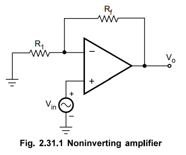
Consider
the noninverting amplifier with resistive feedback as shown in the Fig. 2.31.1.
The
open loop gain of the op-amp is frequency dependent and can be denoted as
AOL(f). To determine the stability of such circuit, it is necessary to
represent the circuits in the standard form of a block diagram, as shown in the
Fig. 2.31.2
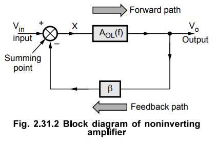
The
block between output and input is called forward block while the block between
output signal and the feedback is called feedback block. The transfer function
or gain of forward block is AOL(f) while the transfer function or
gain of feedback block is β. Let us investigate the stability of such a system
with the help of frequency response approach.
Key Point The feedback
block uses only resistive elements and hence its transfer function P is
independent of frequency and is constant.
From
the Fig. 2.31.2 we can write,
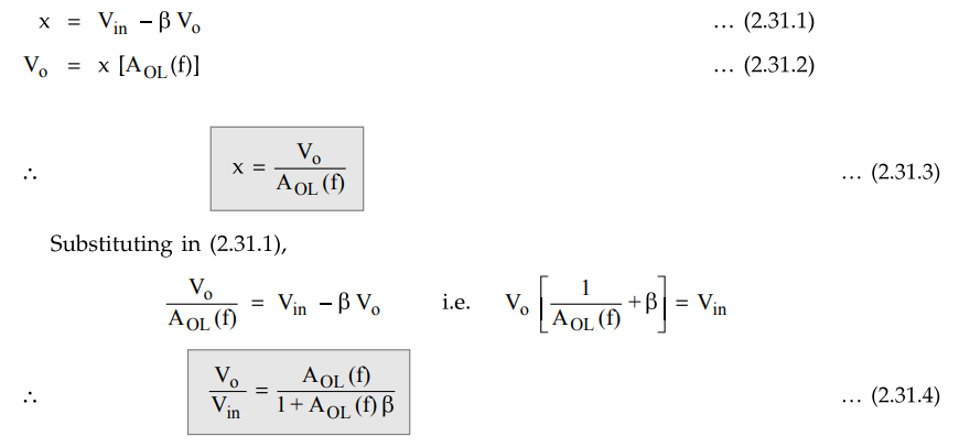
The
ratio Vo/Vin with feedback is called closed loop gain of
the amplifier while the product AOL(f) β is called loop gain which
is generally used to determine the stability.
The
stability of the circuit entirely depends on the behaviour of the roots of the
characteristic equation of the system, which is
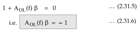
This
can be expressed in the complex form as
AOL(f)
β
= - 1 + j0
From
this, the conditions for the sustained oscillations can be obtained. Equating
angles and magnitudes of both sides of the equation (2.31.7) we get,
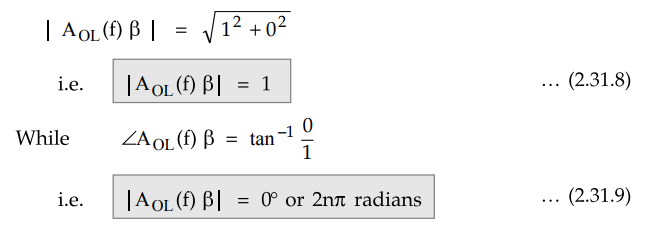
The equation (2.31.8) is the magnitude condition while the equation (2.31.9) is the angle condition. At a particular frequency, both the conditions may get satisfied and there is every possibility that the amplifier may begin to oscillate. These conditions are called Barkhausen Criterion for the sustained oscillations.
Now
oscillations is the verge of instability. The system is said to be stable if
its output reaches a fixed value within a finite time. While if output
increases with time indefinitely or there is output without input, the system
is said to be unstable.
Key Point So determining
stability of the circuit means actually deciding how close the circuit is to
the conditions of sustained oscillations which indicates the starting point of
instability.
This
is possible from the frequency response of the circuit by defining certain
specifications.
1. Stability Specifications from Frequency Response
The
loop gain AOL(f) β is used to obtain the frequency response of the
system over a desired range of frequency, as mentioned earlier. Once the
magnitude plot and phase angle plot (Bode plot) is obtained, the following
specifications are determined, from which system stability can be decided.
i)
Gain Cross Over Frequency (ωgc) :
The
frequency at which the loop gain magnitude (|AOL(f) β) is unity ie-
20 log | AOL(f) β | = 0 dB is called gain cross over frequency and
denoted as ωgc.
ii)
Phase Cross Over Frequency (ωpc) :
The
frequency at which the phase shift introduced by the loop gain is -180° or nπ
radians is called phase cross over frequency and denoted as ωpc.
iii)
Gain Margin (G.M.) :
The
critical values of loop gain are 0 dB and -180° from the stability point of
view. How far away the circuit is from this point of instability can be decided
by determining loop gain at phase cross over frequency. This gain measured at
the frequency ω = ωpc is called gain margin. So loop gain | AOL(f)
β | measured at to = ω = ωpc is the gain margin of the circuit.
Mathematically it can be expressed as
G.M
= - 20 log |AOL(f) β | ω = ωpc dB …. (2.31.10)
iv)
Phase Margin (P.M.) :
Similar
to the gain at phase cross over frequency, one more specification can be
defined from the phase shift of loop gain existing at gain cross over
frequency. This specification is called phase margin.
The
amount by which angle of the loop gain (∠AOL(f)
β | ω = ωgc) differ from the -180o phase shift, at ω = ωgc
is called phase margin. Mathematically it is expressed as
P.M
= 180o + ∠AOL(f)
β | ω = ωgc …. (2.31.11)
2. Stability Criterion
When
ω = ωgc = ωpc,
both angle and magnitude conditions as per Barkhausen criterion get satisfied
and circuit oscillates. The system in such a case is called marginally stable.
If
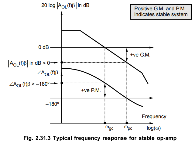
G.M. is positive i.e. gain | AOL(f) β | in dB is negative at ω = ωpc , the system is said to be stable.
Similarly if P.M. is positive i.e. | AOL(f) β | is greater than
-180°, the system is said to be stable.
The
negative values of G.M. and P.M., indicate instability of the system.
Key
Point More positive are the values of G.M. and P.M.,
more stable is the system.
The
Fig. 2.31.3 shows the positive G.M. and P.M. for the stable system on the
frequency response.
Review Questions
1. Write a note on stability criteria for op-amp.
2. What is the stability of an op-amp ? Explain the various
stability specifications.
Linear Integrated Circuits: Unit II: Characteristics of Op-amp : Tag: : - Stability of an Op-amp
Related Topics
Related Subjects

Linear Integrated Circuits
EE3402 Lic Operational Amplifiers 4th Semester EEE Dept | 2021 Regulation | 4th Semester EEE Dept 2021 Regulation