Electric Circuit Analysis: Chapter - 1: Basic Circuit Analysis - DC
Star Delta and Delta Star Conversion
Circuit Diagram, Formula, Solved Example Problems
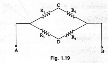
Consider the circuit in figure 1.19. The total effective resistance between A and B is easily found since R1 and R2 are in series and R3 and R4 are also in series.
STAR DELTA AND DELTA - STAR CONVERSION
Consider
the circuit in figure 1.19. The total effective resistance between A and B is
easily found since R1 and R2 are in series and R3
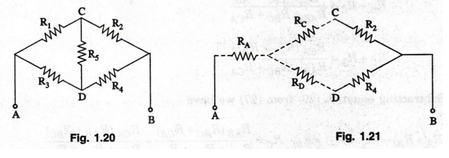
and R4 are also in series. The two combinations are in parallel. If
a resistor R5 is now added between CD as in figure 1.20, the
resistance between A and B cannot be found out as easily as before.
However,
if we can convert the three resistors R1, R5 and R3
which form a closed loop, (also called a Δ) in to a star (Y) as shown in dotted
lines, then RA, RC and RD can replace R1, R5 and R3.
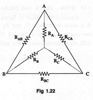
This is shown in figure 1.21. It is easy to calculate the effective resistance
between A and B now. (Rc + R2) is in parallel with (RD
+ R4). This parallel combination is in series with RA.
Delta
to star conversion
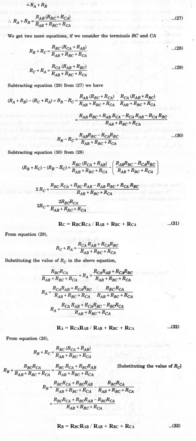
Let
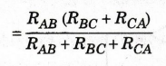
the three resistors RAB, RBC and RCA from a A. It is required to convert this
into its equivalent Y consisting of RA, RR and RC.
This implies that for all purposes, the resistors RAB, RBC and RCA can be the
replaced at terminals, A, B and C by RA, RB and RC. So, the problem reduces to
finding out the values of Y i.e. the values of RA, RB and
RC, for a given RAB, RAB and RCA.
It is shown in figure 1.22.
To
do this, we start by finding out the equivalent resistance between A and B in
the A and Y.
For
the Δ, the effective resistance between A and B is the equivalent of RAB,
in parallel with the series combination of RBC and RCA.
Effective
resistance between A and B in the Δ.
The
effective resistance between A and B in the Y
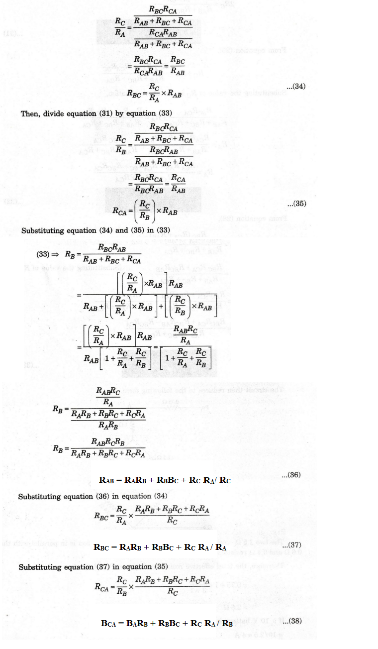
Star
to delta conversion
To
obtain the relationships necessary in the conversion from star to delta, first
divide equation (31) by equation (32).
EXAMPLE
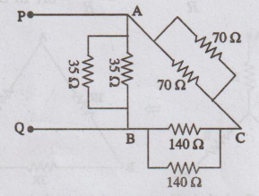
77: In the Wheatstone bridge circuit of figure find the effective resistance
between PQ. Find the current supplied by a 10 V battery connected to PQ.
Solution
:
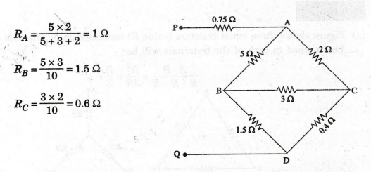
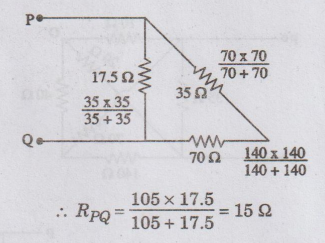
The
circuit then reduces to the following form.
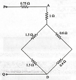
The
two 1.5 Ω resistors are in series and this combination is in parallel with the
0.6
2 and 0.4 Ω resistors which are in series.
Therefore,
the total effective resistance between P and Q. gnited adve
=
0.75 + 1 + (3 × 1) / ( 3 × 1)
=
2.5 Ω
If
a 10 V battery is attached to PQ, current drawn
10/2.5
= 4 A
EXAMPLE
78:
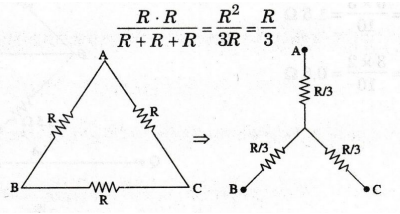
Transform a set of identical resistors connected (a) in A to Y and (b) in Y
to Δ.
Solution:
(a)
Figure shows three equal resistors (value R) connected in A. The star
equivalent to be attached to each of the terminals will be
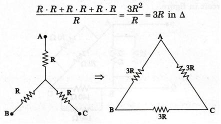
(b)
Figure shows the three resistor in Y. The equivalent is
EXAMPLE
79:
In figure, find the effective resistance between P and Q by Star – Delta conversion.

Converting
the 102, 2002 and 40 Q resistors forming a Y at A (star-point) in to a A, we
have the circuit in figure.
The
resistance between P and Q is calculated from figure as
EXAMPLE
80:
In the circuit given in figure, find the effective resistance between A and
B.
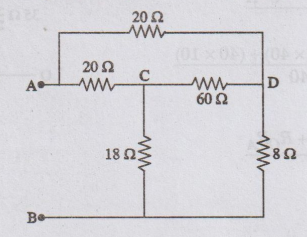
Solution:
This
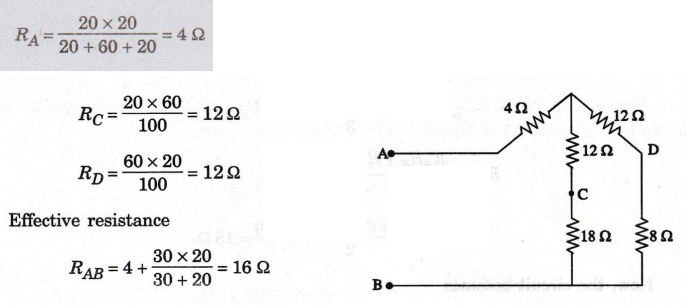
problem can be solved by converting the two 20 22 and 60 22 resistors in A into
a Y as shown in figure. The values of the equivalent Y are
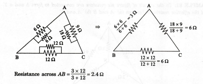
EXAMPLE
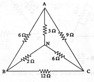
81:
In the circuit of figure six resistors are connected to form Δ and a Y. Find
the effective resistance between (a) A and B (b) A and N.
Solution
:
(a)
Convert the star connected resistor (29, 30 and 60) to delta. It is shown in
figure.
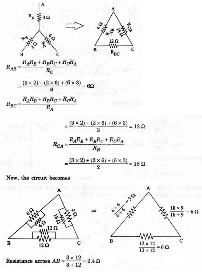
Now,
the circuit becomes
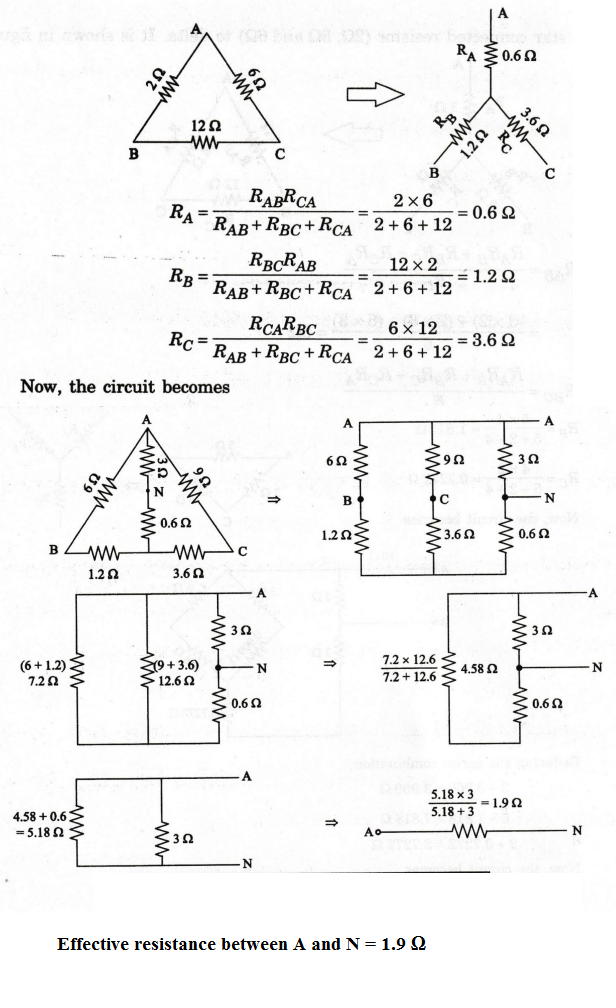
(b)
To find the effective resistance between A and N, convert the 29, 69 and 129
forming a Δ to Y
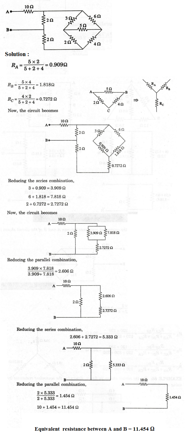
EXAMPLE 82: Find the equivalent resistance between A and B of the circuit shown in figure.
EXAMPLE
83:
Convert the given A network in to star connection.
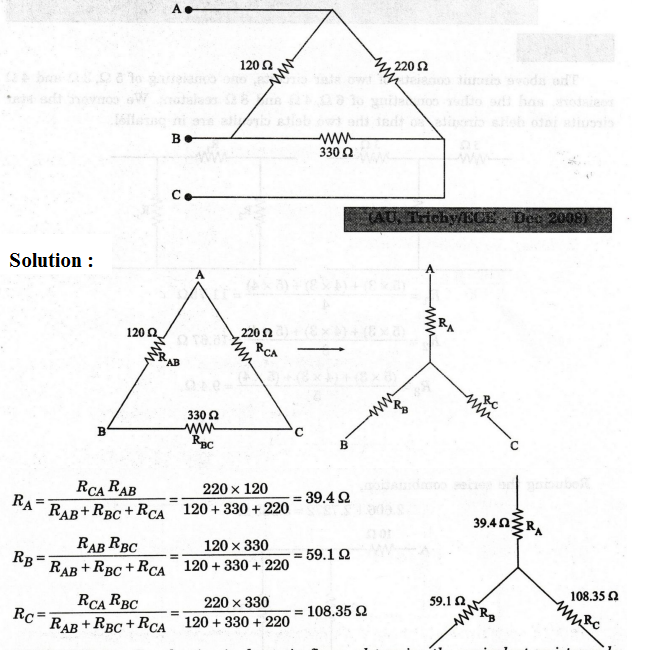
EXAMPLE
84:
For the circuit shown in figure, determine the equivalent resistance by
using star-delta transformation.
Solution
:
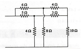
The
above circuit consists of two star circuits, one consisting of 5 Ω, 3 Ω and 4 Ω
resistors, and the other consisting of 6 Ω, 4 Ω
and 8 Ω
resistors. We convert the star circuits into delta circuits, so that the two
delta circuits are in parallel.
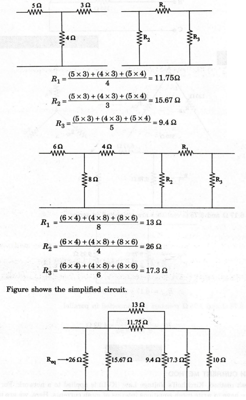
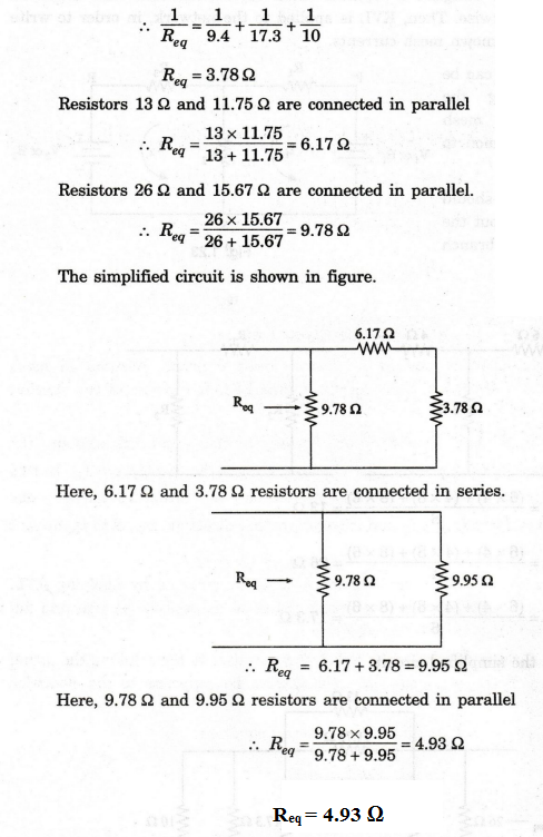
In
the above circuit, the three resistors, 9.4 Ω, 17.3 Ω
and 10 Ω are connected in parallel.
Electric Circuit Analysis: Chapter - 1: Basic Circuit Analysis - DC : Tag: : Circuit Diagram, Formula, Solved Example Problems - Star Delta and Delta Star Conversion