Microprocessors and Microcontrollers: Unit V: (a) Microcontroller Applications
Stepper Motor Control
Review Questions 1. Draw the schematic for interfacing a stepper motor with 8051 microcontroller and write 8051 ALP for changing speed and direction of motor. AU : May-07, Marks 16 2. Explain the microcontroller 8051 based stepper motor control. AU : May-08,10,12, Dec.-10, Marks 16 3. Write an assembly program in 8051 to rotate the stepper motor in clock wise and anticlockwise direction. AU : May-09, Dec.-11, Marks 16 4. Write a program to generate pulses to drive and for continuous operation of a stepper motor. AU : May-12, Marks 8 5. Explain how to control the speed of the stepper motor using 8051 microcontrollers, with algorithmic AU : Dec.-12, Marks 8 6. Describe with a neat diagram the stepper motor control using microcontroller. AU : May-13, Marks 16 7. Explain how to control a stepper motor using 8051 microcontroller with a neat interfacing diagram and assembly program. AU : Dec.-15, May-17, Marks 16
Stepper Motor Control
AU
Dec.-10, 11,12,13,14,15,18,19, May-07, 08,09, 10, 12,13, 16,17,18
A
stepper motor is a digital motor. It can be driven by digital signal. Fig.
17.4.1 shows the typical 2 phase motor interfaced using 8051. Motor shown in
the circuit has two phases, with center-tap winding. The center taps of these
windings are connected to the 12 V supply. Due to this, motor can be excited by
grounding four terminals of the two windings. Motor can be rotated in steps by
giving proper excitation sequence to
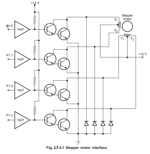
these
windings. The lower nibble of port 1 of the 8051 is used to generate excitation
signals in the proper sequence.
The
Table 17.4.1 shows typical excitation sequence. The given excitation sequence
rotates the motor in clockwise direction. To rotate motor in anticlockwise
direction we have to excite motor in a reverse sequence. The excitation
sequence for stepper motor may change due to change in winding connections.
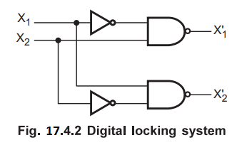
However, it is not desirable to excite both the ends of the same winding
simultaneously. This cancels the flux and motor winding may damage. To avoid
this, digital locking system must be designed. Fig. 17.4.2 shows a simple
digital locking system. Only one output is activated (made low) when properly
excited; otherwise output is disabled (made high).
The excitation sequence given in Table 17.4.1 is called full step sequence.
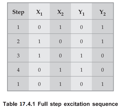
In
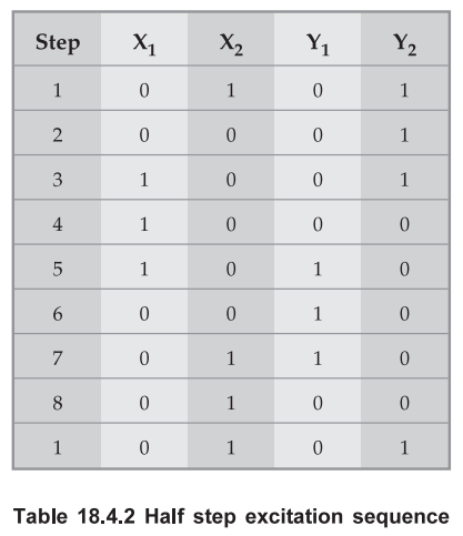
which excitation ends of the phase are changed in one step. The excitation sequence
given in Table 17.4.2 takes two steps to change the excitation ends of the
phase. Such a sequence is called half step sequence and in each step the motor
is rotated by 0.9°.
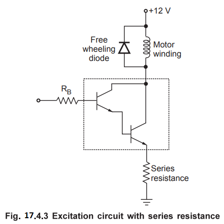
We
know that stepper motor is stepped from one position to the next by changing
the currents through the fields in the motor. The winding inductance opposes
the change in current and this puts limit on the stepping rate. For higher
stepping rates and more torque, it is necessary to use a higher voltage source
and current limiting resistors as shown in Fig. 17.4.3. By adding series
resistance, we decrease L/R time constant, which allows the current to change
more rapidly in the windings. There is a power loss across series resistor, but
designer has to compromise between power and speed.
Example
17.4.1 Write an 8051 assembly language program to
control stepper motor using connections given in Fig. 17.4.1.
Solution:
MOV
R0 # COUNT ; Initialize rotation count
AGAIN:
MOV DPTR, #ETC ; Initialize pointer to excitation code table
MOV
R1, #04 ; Initialize counter to excitation code sequence
BACK:
MOVX A, @DPTR ; Get the excitation code
MOV
P1, A ; send the excitation code
LCALL
DELAY ; Wait for some time
INC
DPTR ; Increment pointer
DJNZ
R1, BACK ; Decrement R1; if not zero goto BACK
DJNZ
RO, AGAIN ; Decrement R0; if not zero goto AGAIN
RET
ORG
3000H
ETC
DB 03H,06H,09H,0CH ; code sequence for clockwise rotation
Example
17.4.2 Write assembly language program to control
conveyer belt using stepper motor and 8051 controller. Belt moves continuously
at rate of 1 step/sec. but stops for 5 sec. when external interrupt occurs and
then continues to move.
Solution
:
MAIN
: MOV IE, #1000 0001B ; Enable external interrupt 0
AGAIN
: MOV DPTR,#ETC ; Initialize pointer to excitation code table
MOV
R1, #04 ; Initialize counter to excitation code sequence
BACK
: MOVX A, @DPTR ; Get the excitation code
MOV
P1, A ; send the excitation code
MOV
A,#14H ; Initialize count = 20
LCALL
DELAY ; Wait for 1sec
INC
DPTR ; Increment pointer
DJNZ
R1, BACK ; Decrement RI if not zero goto BACK
SJMP
AGAIN ; Repeat
ORG
3000H
ETC
DB 03H.06H, 09H, 0CH ; Code sequence for
;
Clockwise rotation
Assume
external interrupt INT0 is used.
ORG
0003H
MOV
A,#64H ; Initialize count =100
ACALL
DELAY ; Called delay routine
RETI
; Return to main program
Delay
Routine
DELAY:
MOV TMOD, #01 ; Time 0, model (16-bit mode)
MOV
R0,A ; Read count and Initialize
BACK:
MOV TL0,#B0H ; TL0=B0H, the low byte
MOV
TH0,#3CH ; TH0=3CH, the high byte
SETB
TR0 ; Start the timer 0
RERE:
JNB TF0,REPE ; Check timer 0 flag untilit rolls over
CLR
TR0 ; Stop timer 0
CLR
TF0 ; clear timer 0 flag
DJNZ
R0, BACK ; Decrement counter and
RET
; if not zero repeat
Note Timer 0 gives a delay
of 50 ms.
Therefore,
to get delay of 1 sec = 50 ms × 20
We
load 20 as a count and to get delay of 5 sec. = 50 ms × 100
Example
17.4.3 A switch is connected to pin P2.7. Write a ALP
to monitor the status of SW and perform the following.
i)
If SW = 0, the stepper motor moves clockwise
ii)
If SW = 1, the stepper motor moves counter clockwise
Solution
:
ORG
00H ; Starting address
MAIN
: SETB P2.7 ; Make it an input
MOV
DPTR, #ETC ; Initialize base pointer to excitation code table
MOV
R0, #00H ; Initialize pointer to excitation code table
BACK
: JB P2.7, ACW ; Check switch status
CJNZ
R0, #04, NEXT ; Roll over the sequence code
MOV
R0, #00H
NEXT
: MOV A, R0 ; Copy pointer in A
MOVC
A, @A + DPTR ; Get the code to rotate clockwise
MOV
P1, A ; Send code to port 1
LCALL
Delay ; Wait for some time
INC
R0 ; Point to next code
SJMP
BACK ; Repeat
ACW
: CJNZ R0, #0FFH, NEXT1 ; Roll over the sequence code
MOV
R0, #03H
NEXT1:
MOV A, R0 ; Copy pointer in A
MOVC
A, @A + DPTR ; Get the code to rotate anticlockwise
MOV
P1 A ; Send code to port 1
LCALL
Delay ; Wait for some time
INC
R0 ; Point to previous code
SJMP
BACK ; Repeat
ACW
: CJNZ R0, #0FFH, NEXT1 ; Roll over the sequence code
MOV
R0, #03H
NEXT1
: MOV A, R0 ; Copy pointer in A
MOVC
A, @A + DPTR ; Get the code to rotate anticlockwise
MOV
P1, A ; Send code to port 1
LCALL
Delay ; Wait for some time
DEC
R0 ; Point to previous code
SJMP
BACK ; Repeat
Delay
: MOV R2, #100
AGAIN1
: MOV R3, #255
AGAIN
: DJNZ R3, AGAIN
DJNZ
R2, AGAIN
RET
ORG
0100H
ETC DB 05H, 06H, 0AH, 09H
Review Questions
1. Draw the
schematic for interfacing a stepper motor with 8051 microcontroller and write
8051 ALP for changing speed and direction of motor. AU : May-07, Marks
16
2. Explain the
microcontroller 8051 based stepper motor control. AU : May-08,10,12,
Dec.-10, Marks 16
3. Write an assembly
program in 8051 to rotate the stepper motor in clock wise and anticlockwise
direction. AU : May-09, Dec.-11, Marks 16
4. Write a program
to generate pulses to drive and for continuous operation of a stepper motor. AU : May-12, Marks 8
5. Explain how to
control the speed of the stepper motor using 8051 microcontrollers, with
algorithmic AU : Dec.-12, Marks 8
6. Describe with a
neat diagram the stepper motor control using microcontroller. AU : May-13, Marks
16
7. Explain how to
control a stepper motor using 8051 microcontroller with a neat interfacing
diagram and assembly program. AU : Dec.-15, May-17,
Marks 16
8. Explain the
stepper motor control using 8051 and write an assembly language program for
running the stepper motor in clockwise direction. AU : May-12, Marks
16
9. Show how to
interface a stepper motor to 8051 microcontroller. Also, write an assembly
language program to demonstrate control of direction and speed of stepper motor
rotation. AU : Dec.-19, Marks 13
10. Interface the
stepper motor with 8051 and explain its operation of stepper motor with neat
diagram and program to rotate in clockwise direction. AU : May.-18, Marks
13
11. Design a stepper motor control system using 8051 microcontroller. AU : Dec.-18, Marks 15
Microprocessors and Microcontrollers: Unit V: (a) Microcontroller Applications : Tag: : - Stepper Motor Control