Electrical Machines: Unit IV: Single Phase Transformer
Sumpner's Test (Back to Back Test)
Single Phase Transformer
• The Sumpner's test is another method of determining efficiency, regulation and heating under load conditions. The O.C. and S.C. tests give us the equivalent circuit parameters but cannot give heating information under various load conditions.
Sumpner's
Test (Back to Back Test)
AU: Dec.-16, 19, May-03, 17
•
The Sumpner's test is another method of determining efficiency, regulation and
heating under load conditions. The O.C. and S.C. tests give us the equivalent
circuit parameters but cannot give heating information under various load
conditions. The Sumpner's test gives heating information also. In O.C. test,
there is no load on the transformer while in S.C. test also only fractional
load gets applied. In all in O.C. and S.C. tests, the loading conditions are
absent. Hence the results are inaccurate. In Sumpner's test, actual loading
conditions are simulated hence the results obtained are much more accurate.
Thus Sumpner's test is much improved method of predetermining regulation and
efficiency than O.C. and S.C. tests.
•
The Sumpner's test requires two identical transformers. Both the transformers
are connected to the supply such that one transformer is loaded on the other.
Thus power taken from the supply is that much necessary for supplying the
losses of both the transformers and there is very small loss in the control
circuit.
•
While conducting this test, the primaries of the two identical transformers are
connected in parallel across the supply V1. While the secondaries
are connected in series opposition so that induced e.m.f.s in the two
secondaries oppose each other. The secondaries are supplied from another low
voltage supply are connected in each circuit to get the readings. The
connection diagram is shown in the Fig. 6.19.1.

•
T1 and T2 are two identical transformers. The secondaries
of T1 and T2 are connected in series opposition. So EEF
= EGH i.e. induced in two srb secondaries are equal but the
secondaries are connected such that E is connected to G and F is connected to
H. Due to such series opposition, two e.m.f.s act in opposite direction to each
other and cancel each other. So net voltage in the local circuit of secondaries
is zero, when primaries are excited by supply 1 of rated voltage and frequency.
So there is no current flowing in the loop formed by two secondaries. The
series opposition can be checked by another voltmeter connected in the
secondary circuit as per polarity test. If it reads zero, the secondaries are
in series opposition and if it reads double the induced e.m.f. in each
secondary, is necessary to reverse the connections of one of the secondaries.
•
As per superposition theorem, if V2 is assumed zero then due to
phase opposition no current flows through secondary and both the transformers T1,
T2 are as good as on no load. So O.C. test gets simulated. The
current drawn from source V1 in such case is 2 I0 where I0
is no load current of each transformer. The input power as measured by
wattmeter W1 thus reads the iron losses of both the transformers.
Pi per transformer = W1 /
2 as T1, T2, are identical.
•
Then a small voltage V2 is injected into the secondary with the help
of low voltage transformer, by closing the switch S. With regulating mechanism,
the voltage V2 is adjusted so that the rated secondary current I2
flows through the secondaries as shown. I2 flows from E to F and
then from H to G. The flow of I1 is restricted to the loop BAIJCDL
KB and it does not pass through W1. Hence W1 continues to read core
losses. Both primaries and secondaries carry rated current so S.C. test
condition gets simulated. Thus the wattmeter W2 reads the total full
load copper losses of both the transformers.
(Pcu)F.L.
per transformer = W2 /2
Key Point:
Thus in the Sumpner's test without supplying the load, full iron loss occurs in
the basol core while full copper loss occurs in the windings simultaneously.
Hence heat run test can be conducted on the two transformers. In O.C. and S.C.
test, both the losses do not occur anolboro simultaneously hence heat run test
cannot be conducted. This is the advantage of Sumpner's test.
From
the test results the full load efficiency of each transformer can be calculated
as,
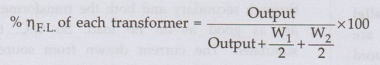
where
Output = VA rating × cos ϕ2
Key Point:
As all the voltages, currents and powers are measured during the test, the
equivalent circuit parameters also can be determined. Hence the regulation at
any load and load power factor condition can be predetermined.
•The
only limitation is that two identical transformers are required. In practice
exact identical transformers cannot be obtained. As two transformers are
required, the test is not economical.
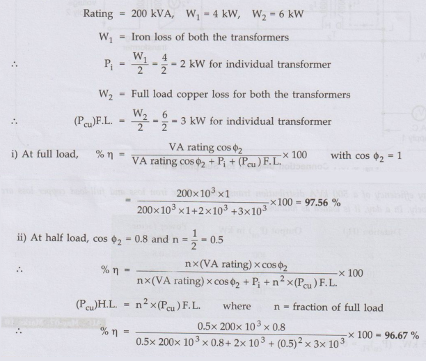
Ex. 6.19.1 Two similar 200 kVA, single phase
transformers gave the following results when tested by Sumpner's test: Mains
wattmeter W1 = 4 kW, Series wattmeter W2 = 6 kW at full load current
Find out individual transformer
efficiencies at,
i) Full load at unity p.f. ii) Half
load at 0.8 p.f. lead
Sol. :
The given values are,
Review Question
1. Explain the back
to back method or Sumpner's test of testing of two identical single phase
transformers. AU: Dec.-16, 19, May-03,17, Marks 8
Electrical Machines: Unit IV: Single Phase Transformer : Tag: : Single Phase Transformer - Sumpner's Test (Back to Back Test)
Related Topics
Related Subjects

Electrical Machines I
EE3303 EM 1 3rd Semester EEE Dept | 2021 Regulation | 3rd Semester EEE Dept 2021 Regulation