Electric Circuit Analysis: Chapter - 2: Network Theorems - DC
Superposition Theorem
Statement, Proof, Circuit Diagram, Formula, Solved Example Problems
"In a linear network containing several sources (including dependent sources), the over all response (branch current or voltage) in any branch in the network equals the algebraic sum of the responses of each individual source considered separately with all other sources made inoperative. i.e replaced by their internal resistances or impedances".
SUPERPOSITION THEOREM
Statement
"In
a linear network containing several sources (including dependent sources), the
over all response (branch current or voltage) in any branch in the network
equals the algebraic sum of the responses of each individual source considered
separately with all other sources made inoperative. i.e replaced by their
internal resistances or impedances".
To
make a source inoperative, it is short circuited leaving behind its internal
resistance or impedance, if it is a voltage source and it is open circuited
leaving behind its internal resistance or impedance, if it is a current source.
Proof
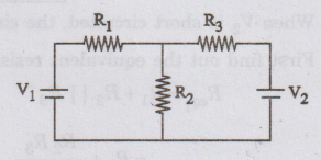
Consider
a simple circuit consisting of two voltage sources E1 or V1 and
E2 or V2.
To
calculate current passing through R2, we can follow either mesh
analysis or superposition theorem.
Mesh
analysis
By
inspection method

Superposition
theorem
Current
flow through R2 due to V1 and V2 = 0
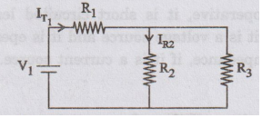
When
V2 is short circuited, the circuit becomes
First
find out the equivalent resistance of the above circuit.

According to Superposition theorem the current passing through R2 due to voltage source V1 and V2 is the sum of the currents passing through R2 due to individual voltage sources V1 and V2.
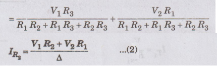
where
Δ = R1 R2 + R1 R3 + R2 R3
Equations
(1) & (2) are the same. Thus, Superposition theorem is verified. This
theorem is valid only for linear systems. This theorem can be applied for
calculating the current through or voltage across a particular element. But,
this Superposition theorem is not applicable for calculation of power.
EXAMPLE
1:
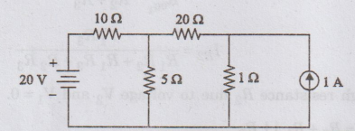
Solve for current through 52 resistor by principle of Superposition theorem.
Solution
:
First,
convert current source into equivalent voltage source.
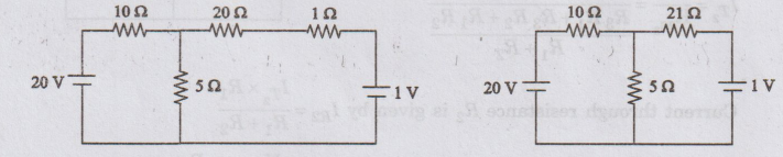

Step
1
15Ω
due to 20V alone (1 V source is short circuited)
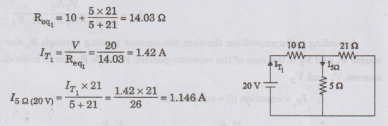
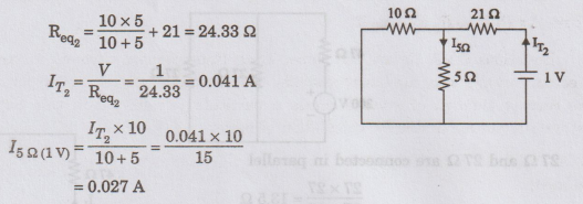
Step
2
I5Ω
due to 1 V alone (20 V source is short circuited)
Step
3
According
to superposition theorem current passing through 5 Ω resistance due to 20 V and
1 V sources is
I5Ω
- I5Ω (20 V) + I5Ω (1V)
=
1.146+0.027 = 1.173 A
I5Ω = 1.173 A
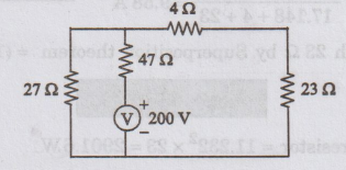
EXAMPLE
2:
Using Superposition theorem, find the current IL and the power
consumed by 23 Ω resistor in the circuit shown in
figure.
Solution
:
First,
open circuit the current source. Now, the circuit becomes
Now
current through 27 Ω resistor is obtained as follows.
4
Ω and 23 Ω are connected in series.
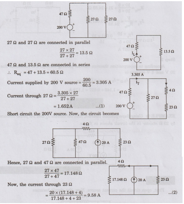
The
total current through 23 Ω by Superposition theorem = (1.652 +9.58) A
I23Ω
=11.232 A
Power
in the 23 Ω resistor = 11.2322 × 23 = 2901.6W
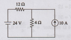
EXAMPLE
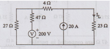
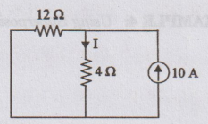
3: Calculate the power dissipated in the 4 2 resistor
given in network, using Superposition theorem.
Solution
Step
I:
Current
source should be open circuited. Now, the circuit becomes
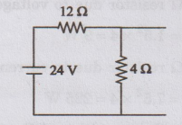
Now,
the current flowing through 4 2 resistor = 24 / 12 + 4 = 1.5 A …. (i)
Step
II:
The
voltage source is short circuited. Now, the circuit becomes
The
current flowing through 4 Ω
=
10 × 12 / 12 + 4 = 7.5 A ….. (ii)
Step
III:
The
total current flowing through 4Ω = 1.5 + 7.5 = 9 A
The
same circuit is analysed by nodal method to verify superposition theorem.
Applying
nodal analysis
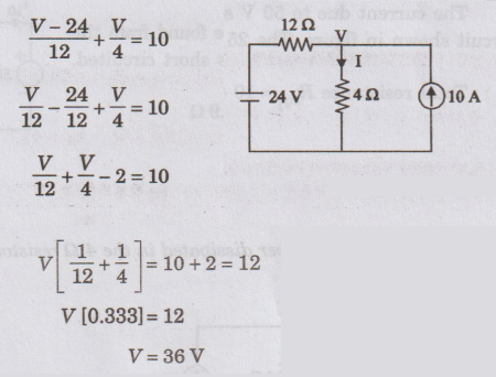
V
= 36 V
The
current passing through the 4 Ω resistor = V / 4 = 36 / = 9A
Thus,
the Superposition theorem is verified.
Power
dissipated in the 4Ω resistor when both the sources are acting simultaneously
is given by
P
= 92 × 4 =324 W
ed
bloode sos
Power
dissipated in the 4 Ω resistor due to voltage source acting alone.
P1
=I2R = 1.52 × 4 = 9W
Power
dissipated in the 4 Ω resistor due to current source acting alone.
P2
= I2R = 7.52 × 4 = 225 W
From
the above results, the Superposition of P1 and P2 gives
=
9 + 225 = 234 W
which
is not equal to P = 324 W
From
this result, the Superposition theorem is not valid for power responses. It is
mainly used for calculating voltage and current responses.
EXAMPLE
4:
Using Superposition principle, find the current in each resistor of given
figure.
Solution
:
The
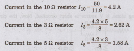
current due to 50 V source can be found from the circuit shown in figure. The
25 V source is short circuited.
Total
resistance Req1 = 10 + 5 × 3 / 5+3 = 11.9 Ω
The
current due to the 25 V source can be found from the circuit shown in figure.
50 V source is short circuited.
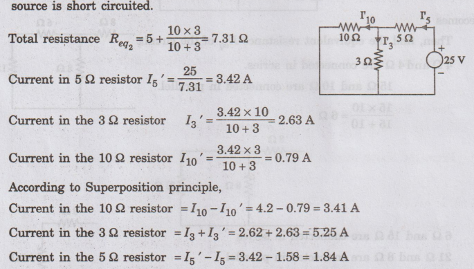
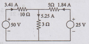
When
both sources are acting, the directions of current are shown in figure.
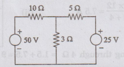
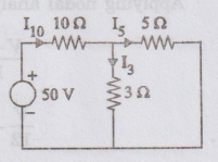
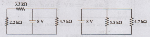
EXAMPLE
5:
Using Superposition theorem, find the current in 10 2 resistor of the network
shown in figure.
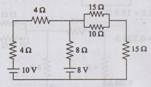
Solution
First,
10 V source is acting alone. 8 V source is short circuited. Now, the circuit
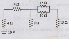
becomes
Then,
find the equivalent resistance Req of the circuit 4 Ω and 4 Ω are
connected in series.
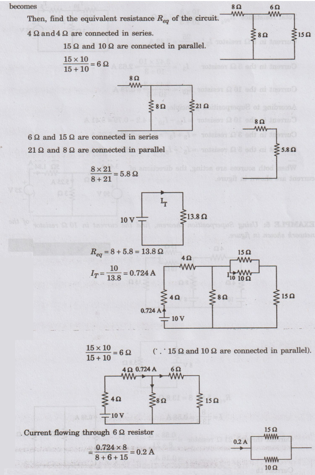
Current
flowing through 6 Ω resistor
= 0.724 × 8 / 8 + 6 + 15 = 0.2 A
Currentthrough
10 Ω resistor (due to 10 V) = 0.2 × 15 / 15 + 10 = 0.12 A
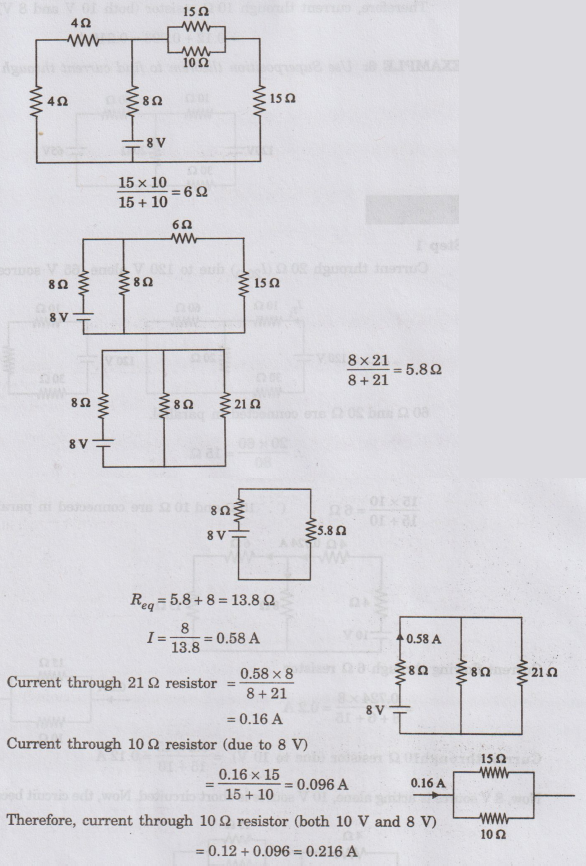
Now,
8 V source is acting alone, 10 V source is short circuited. Now, the circuit
becomes
EXAMPLE
6:
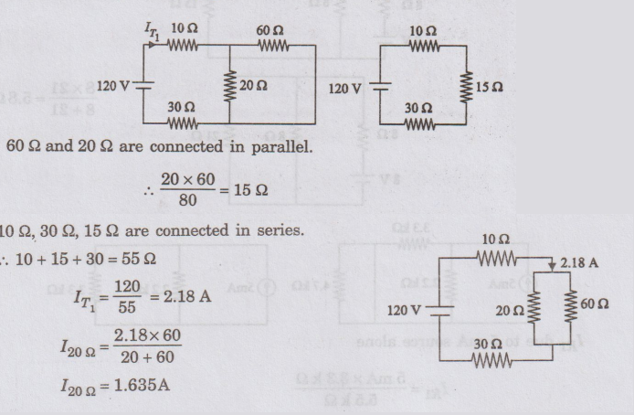
Use Superposition theorem to find current through 20 2 resistance.
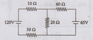
Solution
:
Step
1
Current
through 20 Ω (I20 Ω) due to 120 V alone (65 V source is short
circuited)
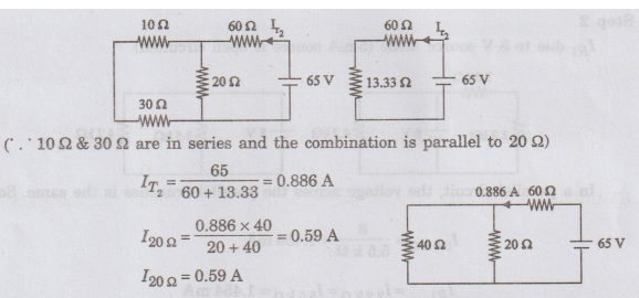
Step
2
Current
through 20 Ω due to 65 V alone (120 V source is short circuited)
Step
3
According
to Superposition theorem current flowing through 202 resistance due to 120 V
and 65 V sources is I20Ω = 1.635 + 0.59 = 2.225 A
I20Ω
= 2.225 A
EXAMPLE
7:
Using Superposition theorem, find the current through R1 for the given network.
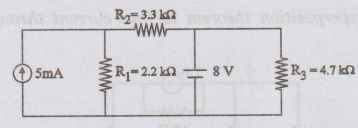
Solution
:
Step
1
Considering
current source alone with voltage source short circuited.
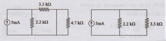
IR1
due to 5 mA source alone
IR1
= 5 mA × 3.3 kΩ / 5.5 k Ω
IR1
= 3 mA
Step
2
IR1
due to 8 V source alone (5 mA source is open circuited)
In
a parallel circuit, the voltage across the parallel branches is the same. So,
I
5.5 kΩ = 8 / 5.5 k Ω = 1.454 mA
IR1(8V)
= I 2.2 k Ω = I5.5 k Ω
= 1.454 mA
According
Superpositiortheorem,
IR1
= 1.454 mA + 3 mA
IR1
= 4.454 mA
EXAMPLE
8:
Use Superposition theorem to find current through RL in the network
given V1 V2 = 10 V.
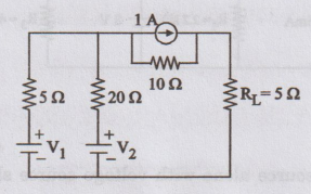
Solution:
Step
- I
V1
alone is acting; V2 is short circuited; 1 A is open circuited.

Step
- 2
V2
alone is acting; V1 is short circuited; 1 A is open circuited.
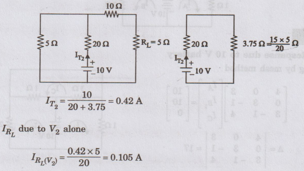
Step
- 3
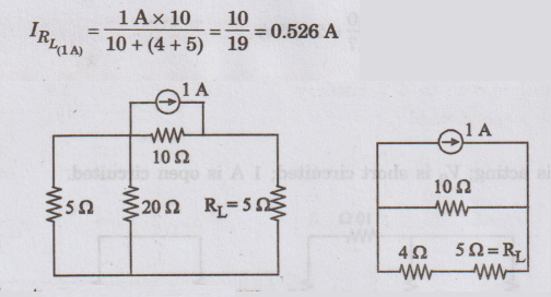
According
to Superposition theorem,
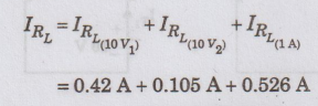
IRL
= 1.05 A
EXAMPLE
9: Find the current in the 22 resistor by
the principle of Superposition.
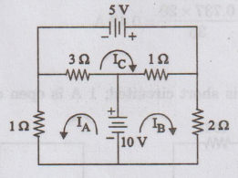
Solution:
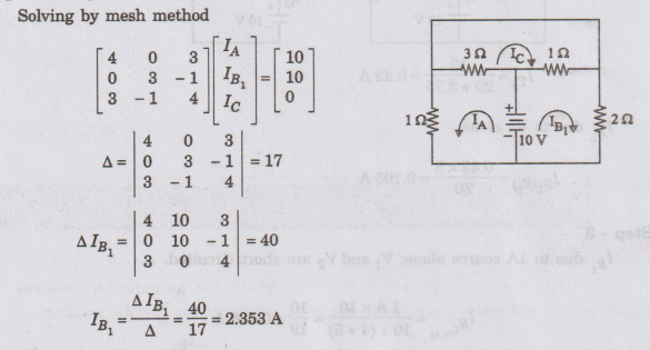
Step
1: Response due to 10 V battery
Solving
by mesh method
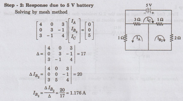
Step
2: Response due to 5 V battery
Solving
by mesh method
Current
through the 2 Ω resistor is
IB
= IB1 + IB2 = 2.353 + 1.176
I2
Ω = 3.53 A
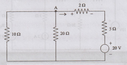
EXAMPLE
10:
Find the voltage across the 22 resistor in figure by using the Superposition
theorem.

Solution
:
Let
us find the voltage across the 2 Ω resistor due to individual sources. The algebraic
sum of these voltages gives the total voltage across the 2 Ω
resistor.
Step
I
First,
find the voltage across 2 Ω resistor due to the 10 V source, while other
sources are set equal to zero. The circuit is redrawn as shown in figure.

Step
II
Next,
find out the voltage across the 2 Ω resistor due to the 20 V source, while the other sources are set equal
to zero. The circuit is redrawn as shown in figure
Assuming
voltage V at node ‘A’ as shown in figure. The current equation is
V
– 20 / 7 + V / 20 + V / 10 = 0
V[0.143
+ 0.05 + 0.1] = 2.86
V
= 2.86 / 0.293 = 9.76 V
The
voltage across the 2 Ω resistor due to
the 20 V source is
V2
= (V-20/7) × 2 = -2.92 V
=
0.73 x 2 = 1.46 V
Step
III
Next,
find the voltage across the 2 Ω resistor due to the 2 A current source, while
the other sources are set equal to zero. The circuit is redrawn as shown in
figure
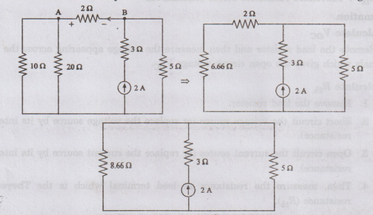
The
current through 2 Ω resistor = 2 × 5 / 5 + 8.66 = 0.73 A
The
voltage across the 2 Ω resistor = 0.73 × 2 = 1.46 V
The
algebraic sum of these voltages gives the total voltage across the 2 Ω resistor
in the network.
V
= 0.97 - 2.92 + 1.46 - 0.49 V
The
negative sign of the voltage indicates that the voltage at 'A' is negative.
Electric Circuit Analysis: Chapter - 2: Network Theorems - DC : Tag: : Statement, Proof, Circuit Diagram, Formula, Solved Example Problems - Superposition Theorem