Electrical Machines II: UNIT II: Synchronous Motor
Synchronous Condensers
This characteristics is similar to a normal capacitor which always takes leading power factor current.
Synchronous Condensers AU
: April-97, Dec.-09, 17, May-11, 12
When
synchronous motor is over excited it takes leading p.f. current. If synchronous
motor is on no load, where load angle 8 is very small and it is over excited (Eb
> V) then power factor angle increases almost upto 90°. And motor rims with
almost zero leading power factor condition. This is shown in the phasor diagram
Fig. 4.19.1.
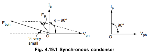
This
characteristics is similar to a normal capacitor which always takes leading
power factor current. Hence over excited synchronous motor operating on no load
condition is called as synchronous condenser or synchronous capacitor.
This is the property due to which synchronous motor is used as a phase advancer
or as power improvement device.
1. Disadvantages of Low Power Factor
In
various industries, many machines are of induction motor type. The lighting and
heating loads are supplied through transformers. The induction motors and
transformers draw lagging current from the supply. Hence the overall power
factor is very low and lagging in nature.
The
power is given by,
P
= V I cos ϕ i.e. I = P / V
cos ϕ ... Single phase
The
supply voltage is constant and hence for supplying a fixed power P, the current
is inversely proportional to the p.f. cos ϕ . Let P = 5 kW is to be supplied
with a voltage of 230 V then,
Case
i)
cos ϕ = 0.8, I - 27.17 A
Case
ii)
cos ϕ = 0.6, I = 36.23 A
Thus
as p.f. decreases, becomes low, the current drawn from the supply increases to
supply same power to the load. But if p.f. maintained high, the current drawn
from supply is less.
The
high current due to low p.f. has following disadvantages :
1.
For higher current, conductor size required is more which increases the cost.
2.
The p.f. is given by
cos
ϕ = Active power / Apparent power = Pin kW
/ S i.e. kVA rating
Thus
for fixed active power P, low p.f. demands large kVA rating alternators and
transformers. This increases the cost.
3.
Large current means more copper losses and poor efficiency.
4.
Large current causes large voltage drops in transmission lines, alternators and
other equipments. This results into poor regulation. To compensate such drop
extra equipment is necessary which further increases the cost.
Key Point : Hence power
factor improvement is must in practice. Hence the supply authorities encourage
consumers to improve the p.f
2. Use of Synchronous Condenser in Power Factor Improvement
The
low power factor increases the cost of generation, distribution and
transmission of the electrical energy. Hence such low power factor needs to be
corrected. Such power factor correction is possible by connecting synchronous
motor across the supply and operating it on no load with over excitation.
Now
let Vph is the voltage applied and Ilph is the current lagging Vph
by angle ϕ1 This power factor ϕ1 is very low, lagging.
The
synchronous motor acting as a synchronous condenser is now connected across the
same supply. This draws a leading current of I2ph
The
total current drawn from the supply is now phasor of Iph and I2ph. This total
current IT now lags Vph by smaller angle due to which effective power factor
gets improved. This is shown in the Fig. 4.19.2.
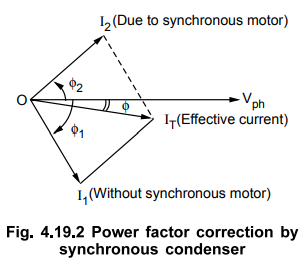
This
is how the synchronous motor as a synchronous condenser is used to improve
power factor of the combined load.
Example
4.19.1 A synchronous motor absorbing 75 kW is
connected in parallel with a factory load of 300 kW having 0.9 lagging power
factor. If the combined load has lagging power factor of 0.95, what is the
value of leading kVAR supplied by the motor and what power factor is it working
?
Solution
:
Load
1 = Industrial load, P1 = 300 kW, cos ϕ1 = 0.9, ϕ1 =
25.8419°
The
power triangle is shown in the Fig. 4.19.3 (a).
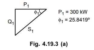
Q1
= P1 × tan ϕ1 = 145.2966 kVAR
This
is reactive power of load 1, lagging nature.
Load
2 = Synchronous motor, P2 = 75 kW
The
combined load active power is PT = P1 + P2 =
375 kW
cos
ϕT = 0.95, ϕT = 18.1948°
The
power triangle is shown in the Fig. 4.19.3 (b).
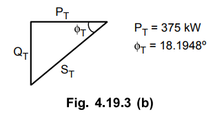
QT
= PT × tan ϕT = 123.2565 kVAR
This
is total reactive kVAR.
QT
= Q1 + Q2 i.e.
123.2565 = 145.2966 + Q2
Q2
= - 22.04 kVAR ... Negative
indicates leading nature
This
is kVAR supplied by synchronous motor and negative sign indicates its leading
nature.
The
power triangle for synchronous motor is shown in the Fig. 4.19.3 (c)
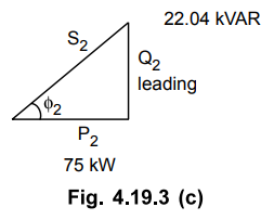
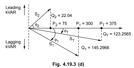
while
overall diagram is shown in the Fig. 4.19.3 (d).
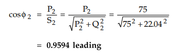
From
Fig. 4.19.3 (c),
Examples
for Practice
Example
4.19.2 An industrial load of 800 kW is operating at 0.6
lagging power factor. It is desired to improve the factor to 0.92 lagging by
connecting a synchronous motor driving a load of 200 kW with an efficiency of
91 %. Determine kVA rating of the synchronous motor and the power factor at
which it is operating
[Ans.:
669.356 kVA, 0.3283 leading]
Example
4.19.3 A synchronous motor improves the power factor of a
load of 500 kW from 0.707 lagging to 0.95 lagging. Simultaneously the motor
carries a load of 100 kW. Find : i) The leading kVAR supplied by the motor ii)
kVA rating of a the motor iii) Power factor at which the motor operates. UPTU : 2008-09
[Ans. : 302.789 kVAR, 318.8753 kVA, 0.3136
leading]
Example
4.19.4 A factory has a total load of 1800 kW at a p.f. of
0.6 lagging. If it is desired to improve the p.f. to 0.95 lagging with the
installation of a synchronous condenser, calculate
i)
the kVA rating of the synchronous condenser.
ii)
total kVA of the factory.
The
condenser does not draw any active power.
VTU : March-03
[Ans.
: - 1808.368 KVAR, 1894.7367 kVA]
Example 4.19.5 A 440 volts, 50 Hz, 3
phase, star-connected circuit takes 35 Amps at a lagging p.f. of 0.8. A star
connected synchronous motor is used to improve the power factor to unity.
Calculate the kVA input, and the power factor of the synchronous motor when it
is also supplying a load of 12 kW and has an efficiency of 85%. VTU : Aug.-05
[Ans.:
Negative sign indicates leading nature., 0.6615 leading, 21.341 kVA]
Review Questions
1. Write a note on synchronous condenser and its use.
2. What are the disadvantages of low p.f. ? How it can be
improved using synchronous condenser ?
3. Explain how synchronous motor can be operated as a
synchronous condensers. Draw a phasor diagram
AU : Dec.-09, 17, May-11, 12, Marks 12
Electrical Machines II: UNIT II: Synchronous Motor : Tag: Engineering Electrical Machines - II : - Synchronous Condensers
Related Topics
Related Subjects

Electrical Machines II
EE3405 Machine 2 EM 2 4th Semester EEE Dept | 2021 Regulation | 4th Semester EEE Dept 2021 Regulation