Electrical Machines II: UNIT I: b. Armature Reaction and Regulation of Alternators
Synchronous Impedance Method or E.M.F. Method
Alternators
The method is also called E.M.F. method of determining the regulation. The method requires following data to calculate the regulation.
Synchronous Impedance Method or E.M.F. Method AU
: Oct.-95, 98, 99, Dec.-04, 06, 07, 12, 14, May-04, 08, 10, 14,
The
method is also called E.M.F. method of determining the regulation. The method
requires following data to calculate the regulation.
1.
The armature resistance per phase (Ra).
2.
Open circuit characteristics which is the graph of open circuit voltage against
the field current. This is possible by conducting open circuit test on the
alternator.
3.
Short circuit characteristics which is the graph of short circuit current
against field current. This is possible by conducting short circuit test on the
alternator.
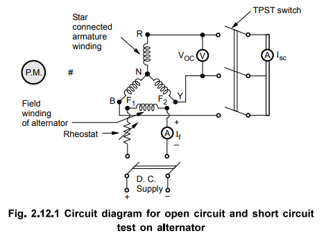
Let
us see, the circuit diagram to perform open circuit as well as short circuit
test on the alternator. The alternator is coupled to a prime mover capable of
driving the alternator at its synchronous speed . the armature is connected to
the switch. The other terminals of the switch are short circuited through an
ammeter. The voltmeter is connected across the lines to measure the open
circuit voltage of the alternator.
The
field winding is connected to a suitable d.c. supply with rheostat connected in
series. The field excitation i.e. field current can be varied with the help of
this rheostat. The circuit diagram is shown in the Fig. 2.12.1.
1. Open Circuit Test
Procedure
to conduct this test is as follows :
i)
Start the prime mover and adjust the speed to the synchronous speed of the
alternator.
ii)
Keeping rheostat in the field circuit maximum, switch on the d.c. supply.
iii)
The T.P.S.T. switch in the armature circuit is kept open.
iv)
With the help of rheostat, field current is varied from its minimum value to
the rated value. Due to this, flux increases, increasing the induced e.m.f.
Hence voltmeter reading, which is measuring line value of open circuit voltage
increases. For various values of field current, voltmeter readings are
observed.
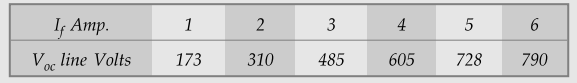
The
observations for open circuit test are tabulated as below :
Observation
table for open circuit test :

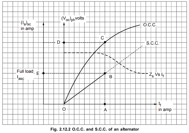
From
the above table, graph of (Voc)ph against If is plotted.
Key Point : This is called
open circuit characteristics of the alternator, called O.C.C. This is shown in
the Fig. 2.12.2
2. Short Circuit Test
After
completing the open circuit test observations, the field rheostat is brought to
maximum position, reducing field current to a minimum value. The T.P.S.T.
switch is closed. As ammeter has negligible resistance, the armature gets short
circuited. Then the field excitation is gradually increased till full load
current is obtained through armature winding. This can be observed on the
ammeter connected in the armature circuit. The graph of short circuit armature
current against field current is plotted from the observation table of short
circuit test. This graph is called Short Circuit Characteristics, S.C.C.
This is also shown in the Fig. 2.12.2.
Observation
table for short circuit test :

The
S.C.C. is a straight line graph passing through the origin while O.C.C.
resembles B-H curve of a magnetic material.
Key Point : As S.C.C. is
straight line graph, only one reading corresponding to full load armature
current along with the origin is sufficient to draw the straight line.
3. Determination of Zs from O.C.C. and S.C.C.
The
synchronous impedance Zs of the alternator changes as load condition
changes. O.C.C. and S.C.C. can be used to determine Zs for any load
and load p.f. conditions.
In
short circuit test, external load impedence is zero. The short circuit armature
is circulated against the impedance of the armature winding which is ZS.
The voltage responsible for driving this short circuit current is internally
induced e.m.f. This can be shown in the equivalent circuit drawn in the
Fig.2.12.3.
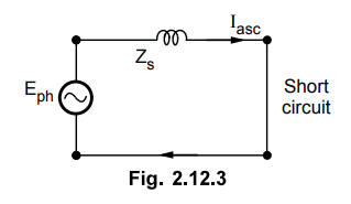
From
the equivalent circuit we can write,
Zs
= E/Iasc
Now
value of Iasc is known, which can be observed on the ammeter. But
internally induced e.m.f. can not be observed under short circuit condition.
The voltmeter connected will read zero which is voltage across short circuit.
To determine Zs it is necessary to determine value of E which is driving
Iasc against Zs.
Now
internally induced e.m.f. is proportional to the flux i.e. field current If.
Eph
oc ϕ oc If ... From e.m.f. equation
So
if the terminals of the alternator are opened without disturbing If
which was present at the time of short circuited condition, internally induced
e.m.f. will remain same as Eph. But now current will be zero. Under this
condition equivalent circuit will become as shown in the Fig. 2.12.4.

It
is clear now from the equivalent circuit that as Ia = 0 the
voltmeter reading (Voc)ph will be equal to internally induced e.m.f.
(Eph).
Eph
= (Voc)ph on open circuit
This
is what we are interested in obtaining to calculate value of Zs. So expression
for ZS can be modified as,

So
O.C.C. and S.C.C. can be used effectively to calculate ZS.
The
value of ZS is different for
different values of If as the graph of O.C.C. is non linear in
nature.
So
suppose ZS at full load is required then,
Iasc
= Full load current
From
S.C.C. determine If required to drive this full load short circuit
Ia. This is equal to 'OA', as shown in the Fig. 2.12.2.
Now
for this value of If, (Voc)ph can be obtained from O.C.C. Extend
line from point A, till it meets O.C.C. at point C. The corresponding (Voc)ph
value is available at point D.

General
steps to determine ZS at any load condition are :
i)
Determine the value of (Iasc) ph for corresponding load condition.
This can be determined from known full load current of the alternator. For half
load, it is half of the full load value and so on.
ii)
S.C.C. gives relation between (Iasc) ph and If.
So for (Iasc) ph required, determine the corresponding value of If from
S.C.C.
iii)
Now for this same value of If, extend the line on O.C.C. to get the
value of (Voc)ph This is (Voc)ph
for same I,, required to drive the selected (Iasc)ph
iv)
The ratio of (Voc) ph and (Iasc) ph, for the
same excitation gives the value of ZS at any load conditions.
The
graph of synchronous impedance ZS against excitation current If
is also shown in the Fig. 2.12.2.
4. Regulation Calculations
From
O.C.C. and S.C.C., Zs can be determined for any load condition.
The
armature resistance per phase (Ra) can be measured by different
methods. One of the method is applying d.c. known voltage across the two
terminals and measuring current. So value of Ra per phase is known.

So
synchronous reactance per phase can be determined.
No
load induced e.m.f. per phase, Eph can be determined by the
mathematical expression derived earlier.

where
Vph = Phase value of rated
voltage
Ia
= Phase value of current depending on the load condition
cos
ϕ = p.f. of load
Positive
sign for lagging power factor while negative sign for leading power factor, Ra
and XS values are known from the various tests performed.
The
regulation then can be determined by using formula,
Regulation
Eph – Vph / Vph × 100
5. Advantages and Limitations of Synchronous Impedance Method
The
main advantage of this method is the value of synchronous impedance ZS
for any load condition can be calculated. Hence regulation of the alternator at
any load condition and load power factor can be determined. Actual load need
not be connected to the alternator and hence method can be used for very high
capacity alternators.
The
main limitation of this method is that the method gives large values of
synchronous reactance. This leads to high values of percentage regulation than
the actual results. Hence this method is called pessimistic method.
The
synchronous impedance is practically variable and not constant. If there is
saturation, it remains constant but it decreases towards the saturation while
it increases for the low saturation region. In synchronous impedance method, in
short circuit test, the field current required is very small to pass the short
circuit current hence the flux density is low and the region is low saturation
region. Hence the synchronous impedance is much higher than its normal value.
Thus the drop IaZs is high due to which the regulation is
also high than the actual value, by synchronous impedance method. Hence the method
is called pessimistic.
Example
2.12.1 The open circuit and short circuit test is
conducted on a 3 phase, star connected, 866 V, 100 kVA alternator.
The
O.C. test results are,
The
field current of 1 A, produces a short circuit current of 25 A.
The
armature resistance per phase is 0.15 Ω. Calculate its full load regulation at
0.8
lagging power factor condition.
Solution
:

For
calculation of Zs on full load, it is necessary to plot O.C.C. and
S.C.C. to the scale.
Note
:
If for same value of If, both Iasc and Voc can
be obtained from the table itself, graph need not be plotted. In some problems,
the values of Voc and Iasc for same If are directly
given, in that case too, the graph need not be plotted.
In
this problem, Iasc = 25 A for
If = 1 A.
But
we want to calculate Zs for
Iasc = Its full load value which is 66.67 A.
So
graph is required to be plotted.
For
plotting O.C.C. the line values of open circuit voltage are converted to phase
by dividing each value by √3.
From
S.C.C., For Iasc = 66.67 A, If = 2.4 A
From
O.C.C., For If = 2.4 A, (Voc) = 240 V

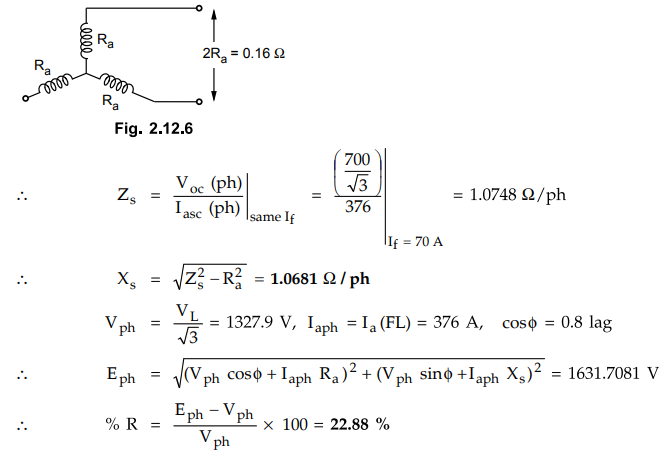
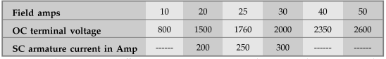
Example
2.12.2 A
3 ph, 1500 kVA, star connected 50 Hz, 2300 V alternator has a resistance
between each pair of terminals as measured by direct current is 0.16 Q. Assume
that the effective resistance is 1.5 times the ohmic resistance. A field
current of 70 A produces a short circuit current equal to full load current of
376 A in each line. The same field current produces an emf of 700 V on open
circuit. Determine the synchronous reactance of the machine and its full load
regulation at 0.8 pfi lag.
Solution
:
1500
kVA, VL = 2300 V
From
the Fig. 2.12.6, Ra = 0.08 Ω /ph
Ra
(effective) = 1.5 × 0.08 Ω /ph
.-.
Ra = 0.12 Ω / ph
Iasc
= 376 A for If = 70 A and Voc (line) = 700 V
For
star connection, line current is same as phase current.
Example
2.12.3 Calculate from the observations taken on a 125 kVA,
400 V, 3 phase alternator, the % regulation for half load condition at 0.8
leading pfi O.C. Test observation :

While
full load current is obtained on short circuit condition at a field current of
8 A. Assume star connection and Ra = 0.1 Ω/ph. The short circuit
current variation with respect to field current is linear.
Solution
:
VL
= 400 V, kVA = 125
kVA
= √3 VL IL × 10-3
125=
√3 × 400 × IL × 10-3
IL
= 180.42 A This is full load current
Iaph
= 180.42 A on full load.
Now
If = 8 A to get Iasc = Ia full load and as If
against Iasc is linear variation to get half load current on short
circuit, the If required is
8/2
= 4 A
The
graph need not be plotted but shown to clear the calculations. Now referring to
O.C. Test observations, without plotting graph we can get Voc value for If
= 4 A, which is 140 V.

Example
2.12.4 From the following test results, determine the
voltage regulation fcy E.M.F. method of a 2000 V, 1 phase alternator delivering
a current of 100 A at i) Unity p.f; ii) 0.8 leading p.f; and iii) 0.71 lagging
p.f. Test results : full load current of 100 A is produced on short circuit by
a field excitation of 2.5 A. An e.m.f. of 500 V is produced on open circuit by
the same excitation. The armature resistance is 0.8 Ω.
Solution
:
Note that the given alternator is single phase hence all the voltage and
currents are obviously per phase and there is no question of line values.

Example
2.12.4 A 3-phase, star-connected, 1000 kVA, 11,000 V
alternator has rated current if 52.5 A. The ac resistance of the winding per
phase is 0.45 Ω. The test results are given below :
OC
Test : field current = 12.5 A, voltage between lines = 422 V.
SC
Test : field current = 12.5 A, line current = 52.5 A
Determine
the full load voltage regulation of the alternator
i)
0.8 pf lagging and ii) 0.8 pf leading.
Solution
:
1000
kVA, VL = 11000 V, Ra = 0.45 Ω

Examples
for Practice
Example
2.12.6 A 2300 V, 50 Hz, 3 phase star connected
alternator has an effective armature resistance of 0.2 Ω. A field current of 35
A produces a current of 150 A on short circuit and an open circuit emf 780 V
(line). Calculate the voltage regulation at 0.8 p.f. lagging and 0.8 p.f.
leading for the full load current of 25 A.
[Ans.:
3.773 %, - 2.924 %]
Example 2.12.7 The open and short circuit test readings for a 3 ϕ - star connected 1000 kVA, 2000 V - 50 Hz synchronous generator are,
The
armature effective resistance is 0.2 ohm per phase. Draw the characteristic
curves and estimate the full load percentage regulation i) 0.8 pf lagging ii)
0.8 power factor leading.
[Ans.:
i) % Reg. = 91.18 %, ii) % Reg. = - 9.29 %]
Example
2.12.8 A 600 V, 60 kVA, single-phase alternator has an
effective resistance of 0.2 Ω. A field current of 10 A produces an armature
current of 210 A on short-circuit and an e.m.f. of 480 V on open-circuit.
Calculate
:
1)
Synchronous impedance and reactance
2)
Regulation with 0.8 p.f. lagging, unity and 0.6 p.f. leading.
VTU
: March-07, Aug.-07
[Ans.:
2.2857 Ω 2.2769 Ω,
28.6 %, 10.08 %, - 23.97 %]
Example
2.12.9 The effective resistance of a 2.2 kV, 50 Hz, 440
kVA, single phase alternator is 0.5 Ω. On short circuit a field current of 40 A
gives a full load current of 200 A. The emf on open circuit with the same field
excitation is 1.16 kV. Find the value of synchronous impedance and find the
voltage regulation at full load and i) Unity power factor ; ii) 0.8 p.f. VTU
: July-12
[Ans.:
17 %, 40.75 %]
Example
2.12.10 A 3 ph, 1500 kVA, star connected 50 Hz, 2300 V
alternator has a resistance between each pair of terminals as measured by
direct current is 0.16 Q. Assume that the effective resistance is 1.5 times the
ohmic resistance. A field current of 70 A produces a short circuit current
equal to full load current of 376 A in each line. The same field current
produces an emf of 700 V on open circuit. Determine the synchronous reactance
of the machine and its full load regulation at 0.8 p.f. lag. VTU :
July-11
[Ans.;
1.0681 Ω / ph 22.88 %]
Example
2.12.11 A 3 phase, 50 Hz, star-connected, 2000 kVA, 2300
V alternator gives a short circuit current of 600 A for a certain field
excitation with the same excitation, the open circuit voltage was 900 V. The
resistance between a pair of terminals was 0.12 Ω. Find the full load
regulation at i) UPF and ii) 0.8 p.f. lagging.
[Ans.:
7.35 %, 23.91 %]
Example
2.12.12 A 100 kVA, 3000 V, 50 Hz, 3 phase star connected
has effective armature resistance of 0.2 Ω. A field current of 50 A produces
short circuit current of 250 A and open circuit emf of 1250 V. Calculate
percentage regulation of 0.8 p.f. lagging and 0.6 p.f. leading. Draw the phasor
diagram for both the conditions.
[Ans.:
% Reg = - 2.4032 %]
Review Questions
1. Explain the synchronous impedance method (EMF method) of
determining the regulation of an alternator.
2. Sketch and explain open circuit and short circuit
characteristics of an alternator.
AU :May-10, Marks 8
3. Why synchronous impedance method is called pessimistic method
?
Electrical Machines II: UNIT I: b. Armature Reaction and Regulation of Alternators : Tag: Engineering Electrical Machines - II : Alternators - Synchronous Impedance Method or E.M.F. Method
Related Topics
Related Subjects

Electrical Machines II
EE3405 Machine 2 EM 2 4th Semester EEE Dept | 2021 Regulation | 4th Semester EEE Dept 2021 Regulation