Microprocessors and Microcontrollers: Unit IV: (f) A/D and D/A Converter Interfacing with 8085
Temperature Control System
A/D and D/A Converter Interfacing with 8085
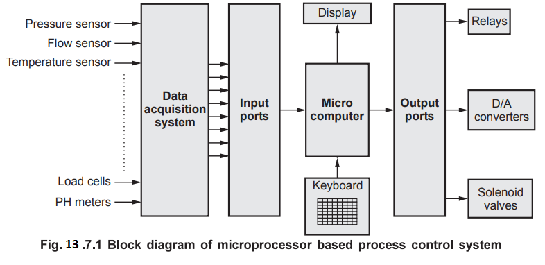
Before going to study the temperature control system, let us see the block diagram of microprocessor based process control system.
Temperature Control System
Before
going to study the temperature control system, let us see the block diagram of
microprocessor based process control system. It is capable of controlling more
than one physical parameter. Such systems are commonly known as data
acquisition and control systems. In these system, analog signals from various
sensors are converted into digital values. These digital values are read in and
processed by the microcomputer. The keyboard and display in the system allow
the user to enter set point values, to read the current values of process
variables, and to issue commands. Relays, D/A converters, solenoid valves, and
other actuators are used to control process variables under program direction.
As
an example, let us study the microcomputer based temperature control system to
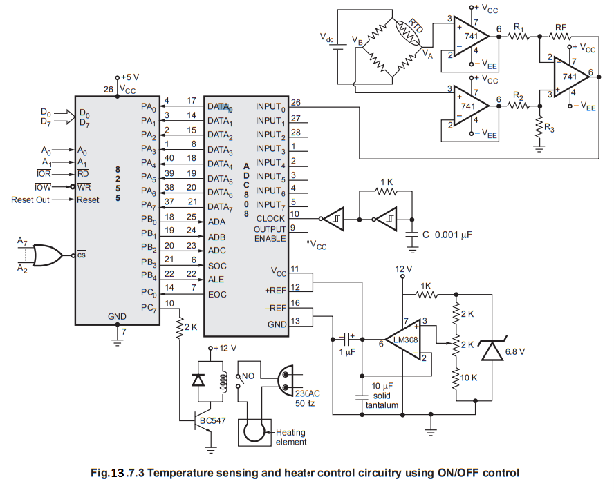
control the temperature between 0-100° C with ON/OFF control. The Fig. 13.7.1
shows the temperature sensing and heater control circuitry using ON/OFF
control. It includes
1.
Sensing circuitry
2.
Analog to digital converter
3.
Circuit required to drive the controller.
1.
Sensing circuitry : The sensing circuitry consists of
instrumentation amplifier using transducer bridge. RTD (Resistance Temperature
Dependent) is used as transducer whose resistance is changed as a function of
temperature.
Rt
= R0 (1 + α Δ t)
Where
Rt is the resistance of RTD at temperature t.
R0
is the resistance of RTD at 0 °C
α
is temperature coefficient of RTD (0.0039)
Δ
t is difference in temperature (t - t0 )
At
0 °C resistance of RTD is 100 Ω and at 100 °C resistance of RTD is
R100
= 100 (1 + 0.0039 (100) ) = 139 Ω
At
0 °C, bridge is balanced so output of bridge (Vab) is 0 V and at 100
°C.
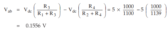
Now
the instrumentation amplifier gain (Rf/R1) must be chosen
to get 5.12 V at 100 °C
Rf/R1
= 5.12 V / 0.1556 = 32.89
If
R1 = 1 K the Rf =
32.89 K. This value of Rf is not available as a standard value so it
is necessary to get this value by adjusting trimpot.
2.
Analog to Digital converter : To convert analog
signal into digital signal 8-bit ADC 0808 is used. ADC 0808 has eight input
channels, so to select desired input channel it is necessary to send 3-bit
address on ADC, ADB and ADA inputs. Port lines PB0 to PB2 are used
for this purpose. Schmitt-trigger inverter circuitry generates 300 kHz clock
which is required to operate ADC 0808. The zener diode and LM 308 amplifier
circuitry is used to produce a VCC and + VREF of 5.12 V
for the A/D converter. With this reference voltage the A/D converter will have
256 steps of 20 mV each.
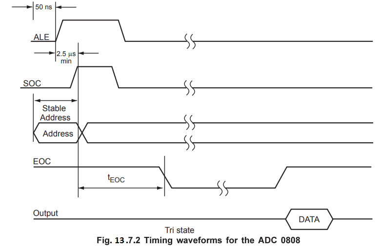
After
at least 50 ns, this address must be latched. This (SOC) is achieved by sending
ALE signal using port line PB4. After another 2.5 µs the start of
conversion must be sent high and then low. Port line PB3 is used for this
purpose. The end of conversion (EOC) is detected by port line PC0. The Fig. 13.7.2
show timing waveforms for the ADC 0808.
3.
Circuit required to drive the controller : As shown in the
Fig. 13.7.3 solid state relay is used to switch ON/OFF heating element. Relay
is energised and deenergised using transistor switch which is controlled by
port line PC7. When PC7 is high, there is a sufficient
base drive to run transistor in saturation (ON) and when PC7 is low, transistor
is in cut off (OFF).
Software
: It
includes
1.
Initialization of 8255
2.
A/D conversion routine
3.
Software required to take control action.
Flowchart
:

Control
Word :
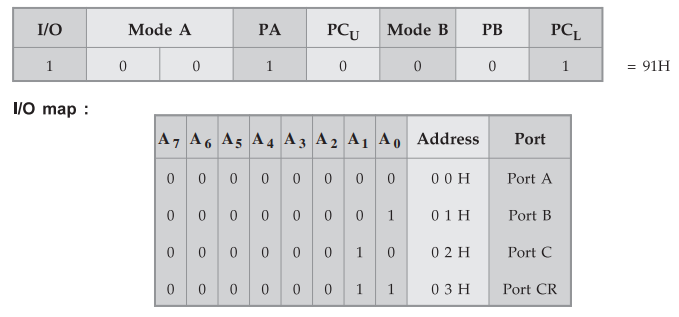
Program
:
MVI
A, 91H
OUT
CR ; Initialize 8255
BEGIN
: CALL CONVERSION ; Call conversion subroutine
CPI
80H ; compare with SETPT (80H)
JC
NEXT
MVI
A, 0EH ; Reset bit PC7 to switch off heater with
OUT
CR ; Bit Set/Reset Mode
JMP
BEGIN
NEXT
: MVI A, 0FH ; Set bit PC7 to switch ON heater with
OUT
CR ; Bit Set/Reset Mode
JMP
BEGIN
Subroutine
Conversion
MVI
A,00H
OUT
PB ; Send address to select input 0
MVI
A, 08H
OUT
PB ; Latch the given address by sending ALE high
MVI
C, 0AH
BACK
: DCR C
JNZ
BACK ; Give delay greater than 2.5 µs
MVI
A, 18H
OUT
PB ; Make SOC high
MVI
A, 08H ; Make SOC low
OUT
PB A, 00H
OUT
PB ; Make ALE low
AGAIN
: IN PC
ANI
01
JZ
AGAIN ; Wait for EOC
IN
PA
RET
Review Questions
1. Describe any
typical automatic process control system using 8085. Use necessary block
diagrams, flow charts, algorithms and program to explain the whole system
operation. AU May-04, Marks 16
2. Write a note on automatic process control. AU May-05, Marks 8
Microprocessors and Microcontrollers: Unit IV: (f) A/D and D/A Converter Interfacing with 8085 : Tag: : A/D and D/A Converter Interfacing with 8085 - Temperature Control System