Microprocessors and Microcontrollers: Unit V: (a) Microcontroller Applications
Temperature Control System
Review Questions 1. Explain the interfacing of sensor with microcontroller. 2. What is signal conditioning?
Temperature Control System
The
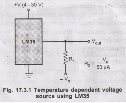
National LM35 is a temperature sensor. It is a temperature-sensitive voltage
source. Its output voltage increases by 10 mV for each °C increase in its
temperature. The Fig. 17.3.1 shows the circuit connection for temperature
sensor LM35. The voltage output from this circuit is connected to a negative
reference voltage, Vs as shown, the sensor will give a meaningful
output for a temperature range of - 55 °C to 150 °C. The output is adjusted
voltage to 0 V for 0 °C. The output voltage can be amplified to give the
voltage range you need for a particular application. The output voltage from
LM35 can be applied to ADC and we can get digital equivalent of analog voltage
corresponding to current temperature.
The
AD590 is another commonly used temperature sensor. It is temperature sensitive
current source. It produces a current of 1 μA/°K. This current can be converter
to voltage source by current to voltage converter. The advantage of current
source sensor is that voltage drop in long connecting wires do not have any
effect on the output value.
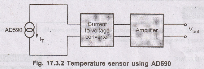
The output of amplifier shown in Fig. 17.3.2 can be applied to ADC to get the digital equivalent of current temperature.
Signal
Conditioning
The
primary objective of industrial process control is to control physical parameters
such as temperature, pressure, flow rate, level, force, light intensity, and so
on. The process control system is designed to maintain these parameters near
some desired specific value. As these parameters can change either
spontaneously or because of external influences, we must constantly provide
corrective action to keep these parameters constant or within the specified
range.
To
control the process parameter, we must know the value of that parameter and
hence it is necessary to measure that parameter. In general, a measurement
refers to the transduction of the process parameter into some corresponding
analog of the parameter, such as a pneumatic pressure, an electric voltage, or
current. A transducer is a device that performs the initial measurement and
energy conversion of a process parameter into analogous electrical or pneumatic
information. Many times further transformation or signal enhancement may be
required to complete the measurement function. Such processing is known as
signal conditioning.
Example
17.3.1 Design a system for temperature measurement
using 89C51 microcontroller along with suitable sensor and signal conditioning.
Display the temperature on LCD. If the temperature rises above 100°C, signal it
using a buzzer. Draw the complete block diagram and flowchart. Also write
algorithm and program for the system. Discuss the hardware and software
requirements in detail.
Solution:
The National LM35 is a temperature sensor. It is a temperature-sensitive
voltage source. Its output voltage increases by 10 mV for each °C increase in
its temperature. The Fig. 17.3.3 shows the circuit connection for temperature
sensor LM35. The voltage output from this circuit is connected to a negative
reference voltage, V, as shown, the sensor will give a meaningful output for a
temperature range of - 55 °C to 150 °C. The output is adjusted to 0 V for 0 °C.
The output voltage can be amplified to give the voltage range you need for a
particular application. The output voltage from LM35 can be applied to ADC and
we can get digital equivalent of analog voltage corresponding to current
temperature.
Since
the ADC0808 has 8-bit resolution with a maximum of 256 (28 steps)
and the LM 35 produc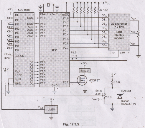 es 10 mV for every degree of temperature change, we can condition
Vin of the ADC0808 to produce a Vout of 2560 mV (2.56 V) for
full-scale output. In order to produce such output we have to set Vref
2.56. this makes Vout of the ADC 0808 correspond directly to the temperature as
monitored by LM 35.
es 10 mV for every degree of temperature change, we can condition
Vin of the ADC0808 to produce a Vout of 2560 mV (2.56 V) for
full-scale output. In order to produce such output we have to set Vref
2.56. this makes Vout of the ADC 0808 correspond directly to the temperature as
monitored by LM 35.
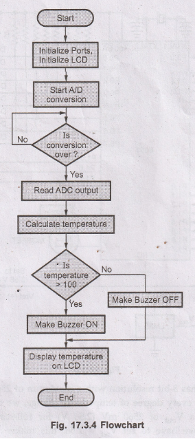
Algorithm
Step
1: Initialize ports
Step
2: Initialize LCD
Step
3: Start A/D conversion
Step
4: Wait for EOC (End of Conversion)
Step
5 : Read digital output of ADC
Step
6: Calculate temperature
Step
7: If temperature is greater than 100 °C make buzzer ON
;
otherwise make buzzer OFF
Step
8: Display temperature on LCD
Step
9 : Repeat steps 3 through 8
Main
Program
MOV
81H, #30H ; Initialize stack
MOV
P3, #0FFH ; Configure port 3 as input
MOV
P2, #0FFH ; Configure port 2 as input
START:
ACALL R_ADC ; Read data from ADC
ACALL
BAC ; Convert binary to ASCII
ACALL
COMT ; If temperature is greater than 100 °C make buzzer ON
;
otherwise make buzzer OFF
ACALL
LCD ; Display it on LCD
SJMP
START ; Repeat
Analog
to Digital Conversion Routine
R_ADC
: CLR P1.3 ; Make SOC low
CLR
P1.4 ; Make ALE low
MOV
A, #00H ; Set address for channel 0
MOV
P1,A ; Get the channel number and set its address
SET
P1.4 ; Send ALE
NOP
; Pulse
CLR
P1.4
SET
P1.3 ; Send start of
NOP
; Conversion
CLR
P1.3 ; Pulse
WAIT
: JB P3.0, WAIT ; Wait for ECO signal
WAIT
: JNB P3.0,WAIT
MOV
A,P2 ; Get digital data
MOV
R5, A ; Binary input
RET
; Return
Binary
to ASCII Conversion Routine
BAC
: MOV A, R5 ; Get binary data
MOV
R0, #40 ; Load RAM address
MOV
B, #10 ; B = 10 (0AH)
DIV
AB ; Divide by 10
MOV@R0,
B ; Save the next digit
INC
R0 ; Increment RAM address
MOV
B, #10 ; B = 10 (0AH)
DIV
AB ; Divide by 10 again
MOV
@R0, B ; Save the next digit
INC
R0 ; Increment RAM address
MOV
@R0, A ; Save the last digit
MOV
R0, #40 ; Load RAM address for decimal
MOV
R1, #50 ; Load RAM address store ASCII data
MOV
R2, #3 ; Initialize counter
BACK:
MOV A, @R0 ; Get decimal digit
ORL
A, #30H ; Make it ASCII
MOV
@R1, A ; Save it
INC
R0 ; Increment RAM address for decimal data
INC
R1 ; Increment RAM address for ASCII data
DJNZ
R2, BACK ; Repeat until the last digit
RET
Compare
Temperature Routine :
COMT
: MOV A, R5 ; Get binary data
CJNZ
A, #101, NEXT ; compare it with 101
NEXT
: JC BOFF ;
SETB
P3.7 ; Make Buffer ON
AJMP
LAST
BOFF
: CLR P3.7 ; if Yes, Make Buzzer OFF
LAST
: RET
LCD
Routine :
LCD
: MOV A,#3CH ; [Send command code to set font = 5×10 dots,
LCALL
COMMAND ; DL = 8-bits and N = 2 lines].
MOV
A,#0EH ; [Send command code to set display
LCALL
COMMAND ; and cursor ON]
MOV
A,#01H ; [Send command code to
LCALL
COMMAND ; clear LCD]
MOV
A,#86H ; [Send command to set DD RAM
LCALL
COMMAND ; address to the seventh location]
MOV
R2,3 ; Initialize counter
MOV
R1,#50 ; Load RAM address of ASCII data
B1
: MOV A,@R1 ; Get ASCII digit
LCALL
DISPLAY ; Display Digits
INC
R1 ; Increment RAM address
DJNZ
R2, B1 ; repeat until the last digit
MOV
A,#”
LCALL
DISPLAY ; Display space
MOV
A,#'K'
LCALL
DISPLAY ; Display letter K
MOV
A,#'g'
LCALL
DISPLAY ; Display letter g
RET
COMMAND
Routine:
LCALL
READY ; Check whether LCD is ready?
MOV
P1, A ; Issue command code
CLR
P1.5 ; Make RS = 0 to issue command
CLR
P1.6 ; Make R/ppppp = 0 to enable writing
SETB
P1.7 ; Make E = 1
CLR
P1.7 ; Make E = 0
RET
; Return
READY
Routine :
CLR
P1.7 ; Disable display
CLR
P1.5 ; Make RS = 0 to access command register
MOV
P0,#0FFH ; Configure P0 as an input port
SETB
P1.6 ; Make R/ppppppp = 1 to enable reading
READ
: SETB P1.7 ; Make E = 1
JB
P0.7,READ ; Check DB7 bit. If it is 1, LCD is busy
;
hence check if until it is 0
CLR
P1.7 ; Make E = 0 to disable display
RET
; Return
DISPLAY
Routine :
LCALL
READY ; Check whether LCD is ready?
MOV
P0; A ; Issue data
SETB
P1.5. ; Make RS = 1 to issue data
CLR
P1.6 ; Make R/ppppppp = 0 to enable writing
SETB
P1.7 ; Make E = 1
CLR
P1.7 ; Make E = 0
RET
; Return
Review Questions
1. Explain the
interfacing of sensor with microcontroller.
2. What is signal conditioning?
Microprocessors and Microcontrollers: Unit V: (a) Microcontroller Applications : Tag: : - Temperature Control System