Transmission and Distribution: Unit III: (a) Mechanical Design of Transmission Lines
Tension and Sag at Erection
Mechanical Design of Transmission Lines
We have seen that there is major difference between the calculation of sag and tension in still air and the calculation of sag and tension under severe atmospheric conditions like ice coating, wind pressure etc.
Tension and Sag at
Erection
We have seen that there is major
difference between the calculation of sag and tension in still air and the
calculation of sag and tension under severe atmospheric conditions like ice
coating, wind pressure etc. The factor of safety is provided for a particular
tension and sag occurring at specific temperature and ice, wind conditions.
These conditions are different than the conditions at the time of erection of
the line.
So if the various values at maximum load
conditions with ice, wind and at low temperature are known, then the
corresponding values at the time of erection conditions without ice, wind and
at normal temperatures, we must able to calculate.
So if the values are known at lowest
temperature of - 5.5 °C then we must able to calculate all the values at the
time of erection of line at (- 5.5 + t) °C.
Let us revise the expressions for the
various parameters derived earlier in the last section,
T = Tension = H
y = wx2 / 2T where w = Weight
of conductor
S = wl2 / 2T where l
= L/2 = Half span length
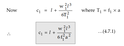
and c = l w2l3
/ 6T2
where c = Actual half span length of
conductor.
Let the values T1, f1,
w1, c1, S1,and t1 are the known
values of tension, stress, equivalent weight, half span conductor length,
maximum sag and temperature respectively under severe conditions including ice
and wind pressure and at - 5.5 °C.
T1= f1 × Area where f1 = Stress in kg/m2
While the values T2, f2,
w2, c2, S2,and t2 are the values
specified at normal erection conditions, without ice and wind pressure and at
normal temperature t2 which are to be calculated.
Let a
= Area of cross-section of conductor
α = Temperature coefficient of conductor
at t1 °C
E - Young's modulus
When the temperature increases from t1
to t2 then the wire gets elongated and the half span length of
conductor changes from c1 to c2.
The increase in the length is given by c1
(t2 - t1) α which can be approximated to (t2
- t1) α l
When the temperature changes from t1
to t2 the stress decreases from f1 to f2.
Correspondingly there is reduction in the length of wire which is given by,
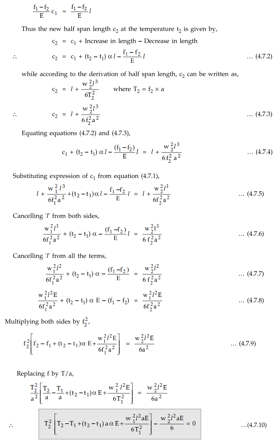
This is cubic equation in T2
which can be solved to obtain tension at the time of erection.
Once T2 is known, sag at
erection time can be obtained as,
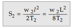
where w2 = Weight of
conductor without ice and wind.
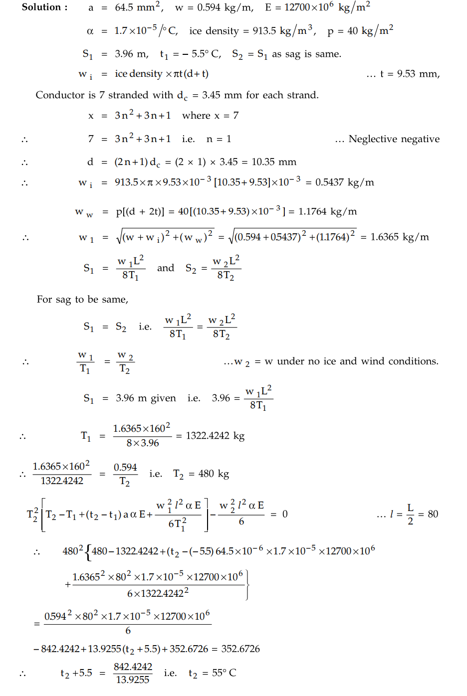
Example 4.7.1 An
overhead line has a span of 160 m of stranded copper conductor between level
supports the sag is 3.96 m at - 5.5° C with 9.53 mm thick in ice coating and
wind pressure of 40 kgf/m of projected area. Calculate the temperature at which
the sag will remain the same under conditions of no ice and no wind. The
particulars of the conductor are as follows : Size of conductor - 7/3.45 mm.
Area of cross section - 64.5 mm2 , weight 2 of conductor - 0.594
kgf/m. Modulus of elasticity - 12700 kgf/mm2 , Coefficient of linear
expansion - 1.7 × 10 /°C. Assume 1 m3 of ice to weight 913.5 kgf.
AU : May-14, Marks 16
Solution :
Review Question
1. Derive an expression for the tension and sag at erection in a overhead transmission line.
Transmission and Distribution: Unit III: (a) Mechanical Design of Transmission Lines : Tag: : Mechanical Design of Transmission Lines - Tension and Sag at Erection
Related Topics
Related Subjects

Transmission and Distribution
EE3401 TD 4th Semester EEE Dept | 2021 Regulation | 4th Semester EEE Dept 2021 Regulation