Electric Circuit Analysis: Chapter - 2: Network Theorems - DC
The Reciprocity Theorem
Statement, Proof, Circuit Diagram, Formula, Limitations, Solved Example Problems
In any linear network containing bilateral linear resistances and energy sources, the ratio of a voltage V introduced in one mesh to the current I in any second mesh is the same as the ratio obtained if the positions of V and I are interchanged, other voltages sources are being removed.
THE RECIPROCITY THEOREM
Statement
In
any linear network containing bilateral linear resistances and energy sources,
the ratio of a voltage V introduced in one mesh to the current I in any second
mesh is the same as the ratio obtained if the positions of V and I are
interchanged, other voltages sources are being removed.
The
reciprocity theorem leads to a definition of the transfer resistance RT where V
is the voltage in mesh 1 and I is the current in any second mesh.
RT12
= V1 / I2 = RT21 = V2 / I1
Proof
Let us consider the network which consists of resistors R1, R2 and R3
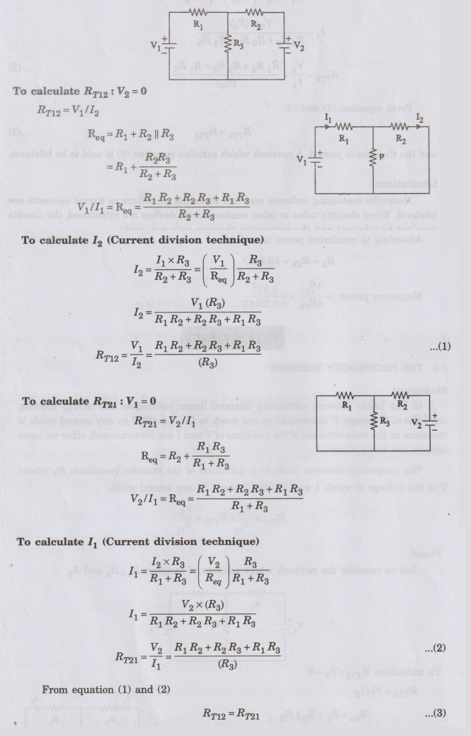
and
the theorem is proved. A network which satisfies equation (3) is said to be
bilateral.
Limitations
Networks
containing ordinary resistors including capacitors as circuit elements are
bilateral. When electron tubes or other semiconductor devices are introduced,
the circuits may not be bilateral and the reciprocity theorem may not apply.
EXAMPLE
37:
In the network shown in figure, find the current in the 82 resistor. Verify
the reciprocity theorem.
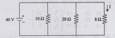
Solution:
Current
through the 8 Ω resistor = 40 / 8 = 5 A
Current
through 10 Ω resistor = 40 / 10 = 4 A
Current
through 20 Ω resistor = 40 / 20 = 2 A
On
changing the voltage source to the 8 Ω branch,
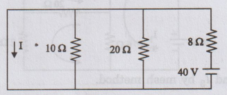
The
current through the short = 40 / 8 = 5 A
Thus,
the reciprocity theorem is verified.
I10
= I20 = 0
EXAMPLE
38:
In the circuit of figure, find I3 and verify the reciprocity
theorem.
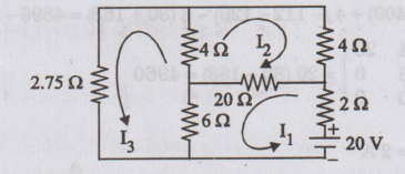
Solution:
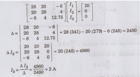
The
current I3 is found by the mesh current method.
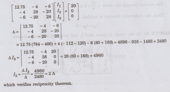
Now,
transferring the battery to the branch with 2.75 Ω resistor, we get the circuit
of figure.
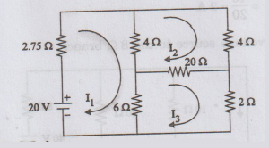
We
shall again find I3 by mesh method.
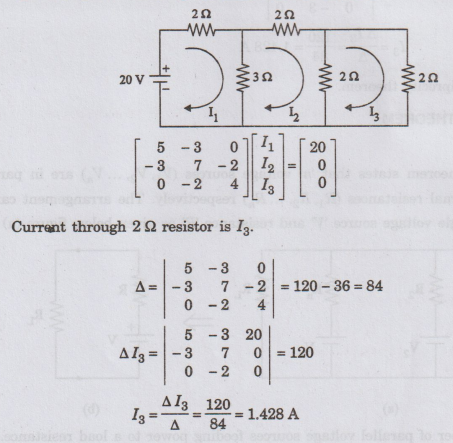
EXAMPLE
39:
Verify the reciprocity theorem for the network shown in figure.
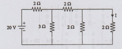
Solution
:
The
current I is found by the mesh current method.
Applying
the reciprocity theorem, by inter changing the source and response, we get
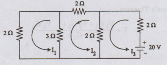
By
applying mesh method, we find the I3.
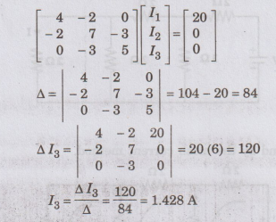
which
verifies reciprocity theorem.
Electric Circuit Analysis: Chapter - 2: Network Theorems - DC : Tag: : Statement, Proof, Circuit Diagram, Formula, Limitations, Solved Example Problems - The Reciprocity Theorem