Basic Civil & Mechanical Engineering: UNIT II: c. Measurement of angles
Theodolite surveying
Measurement of angles
Theodolite is a precise instrument used for measuring horizontal and vertical angles directly in surveying, including determining differences in elevation, extending survey lines, locating points on a survey line, etc.
THEODOLITE SURVEYING
For
measuring angles in survey work, the instruments used are: Compass and Theodolite.
Compass
Vs Theodolite: The compass does not measure the angle
between two lines directly, but measures the angle between the magnetic
meridian and the line. But, the theodolite measures (i) the angle between two
lines directly and (ii) the bearing of the lines.
Uses:
Theodolite is a precise instrument used for measuring horizontal and vertical
angles directly in surveying, including determining differences in elevation,
extending survey lines, locating points on a survey line, etc.
Types
of Theodolite: Theodolite is classified as Transit
Theodolite and Non-transit Theodolite. In the transit theodolite, the line of
sight can be reversed / inverted (i.e., transited) by revolving the telescope
through 180° about a horizontal axis in the vertical plane. It is most widely
used nowadays. In the non-transit theodolite, the telescope cannot be
transited. It is obsolete.
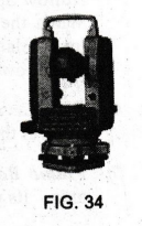
Fig.
34 shows the pictorial view of Transit Theodolite. It is mounted on a Tripod
Stand. The tripod stand consists of three solid or framed legs.
1. TRANSIT THEODOLITE
Description
(Fig. 35)
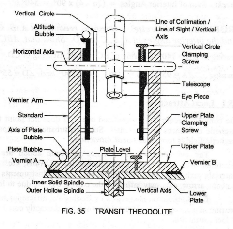
1.
Telescope
The
telescope is mounted on a horizontal spindle, known as Horizontal Horizontal
Axis. The Horizontal Axis is supported on the Standards. The telescope Telescope
is rotated in horizontal or vertical planes to sight the distant objects.
2.
Vertical Circle
It
is connected to the horizontal axis. Hence, the vertical circle rotates when
the telescope is rotated about the horizontal axis. It is graduated from 0° to
360° clockwise.
Vertical
angles are measured by Verniers, fixed diametrically opposite to each other.
Using a Vertical Circle Clamping Screw, the telescope can be set in any desired
position in the vertical plane.
3.
Altitude Bubble: For measuring vertical angles, the
transit theodolite is levelled with reference to the Altitude Bubble.
4.
Upper Plate or Vernier Plate: It is attached to the
Inner Solid Spindle. It carries two verniers A and B, with magnifiers to
magnify the readings. The magnifiers are placed 180° apart for reading
horizontal angles. The upper plate supports the Standard at its upper surface.
It is connected to the Lower Plate.
5.
Lower Plate or Scale Plate: It is a graduated
horizontal circular plate attached to the Outer Hollow Spindle. It is graduated
from 0° to 360° in clockwise direction. When the upper plate is clamped using
Upper Plate Clamping Screw, both the upper and lower plates move together as
one unit. When upper plate is loosened, it rotates with respect to the lower
plate and the vernier readings change.
6.
Plate Levels or Plate Bubbles: Two spirit levels
called Plate Levels or Plate Bubbles are used to level the instrument. They are
fixed at 90° to each other on the upper vernier plates.
7.
Plumb Bob: A Plumb Bob is suspended from the hook
fitted to the bottom of the vertical axis. Its purpose is to center the
theodolite exactly over the station mark.
2. TERMINOLOGY
1.
Centering: It is the process of setting up the
theodolite exactly over a station mark. Centering may be done by plumb bob.
2.
Levelling: It is the process of making vertical
axis of the instrument truly vertical.
3.
Axis of Telescope: It is an imaginary line joining
the optical center of the object glass and the center of the eye piece.
4.
Horizontal Axis: It is an axis about which the telescope
is rotated in a vertical plane. It is also known as Trunnion Axis, Elevation
Axis or Transverse Axis.
5.
Vertical Axis: It is an axis about which the
instrument is rotated in a horizontal plane.
6.
Transiting: Transiting is the process of rotating
the telescope in the vertical plane through 180° about the horizontal axis.
7.
Axis of Plate Level: It is a straight line tangential
to the longitudinal curve of the plate level tube at its center. It is
horizontal when the bubble is centered.
8.
Axis of Altitude Level: It is the straight line tangential
to the longitudinal curve of the altitude level tube at its center. It is
horizontal when the bubble is centered.
9.
Face Left Observation: It is an observation of horizontal
or vertical angle when the face of the vertical circle is to the left of the
observer.
10.
Face Right Observation: It is an observation of horizontal
or vertical angle when the face of the vertical circle is to the right of the
observer.
11.
Changing the Face: It is an operation of bringing the
face of the telescope from face left condition to face right condition or vice
versa. It is achieved by transiting the telescope and then swinging it through
180°.
12.
Line of Sight or Line of Collimation: It is an
imaginary line passing through the intersection of horizontal and vertical
cross-hairs of the diaphragm and the optical center of the object glass.
13.
Swinging the Telescope: It is the process of rotating the
telescope in a horizontal plane.
1.
Fundamental Lines and Their Relations
Following
are the fundamental lines of a transit:
1.
Vertical Axis
2.
Horizontal Axis
3.
Line of Collimation
4.
Axis of Plate Level
5.
Axis of Altitude Level
Desired
Relations: A theodolite in proper adjustment must
have the following relations between fundamental lines:
1.
Axis of Plate Level must be perpendicular to the Vertical Axis.
2.
Horizontal Axis must be perpendicular to the Vertical Axis.
3.
Axis of Altitude Level must be parallel to the Line of Collimation.
4.
Line of Collimation must be perpendicular to the Horizontal Axis.
5.
Vertical Circle Vernier must read zero, when the Line of Collimation is
horizontal.
3. DIRECT METHOD OF
MEASURING HORIZONTAL ∠ POR
A
horizontal angle is the angle formed by two intersecting vertical planes at
their point of intersection. It is measured in the horizontal plane using the
Method of Repetition.
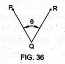
1.
See Fig. 36. To measure the horizontal ∠
PQR between two stations P and R at the instrument station Q, pegs or ranging
rods are erected at P and R.
2.
Theodolite is set at Q, centered and levelled with reference to the plate
levels.
3.
Turn the upper and lower plates in the opposite direction. Set the vernier A to
0 using the upper clamp.
4.
Then clamp both the plates together.
5.
Note the readings of verniers A and B.
6.
Turn the telescope towards the left signal at P. Bisect P using lower tangent
screw.
7.
Then turn the telescope clockwise to bisect signal at R. Bisect R by upper
tangent screw.
8.
Read both verniers to get the approximate value of the angle PQR with one face.
9.
Repeat the above by changing the face of the instrument to right. The mean of
the two vernier readings with different faces gives the average horizontal
angle.
4. DIRECT METHOD OF MEASURING VERTICAL ∠POH
Vertical
angle is the angle made by the inclined line of sight with the horizontal plane
through the horizontal axis.
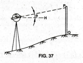
1.
See Fig. 37. P is the object at station Q. Level the instrument with reference
to the plate level.
2.
Turn the instrument about vertical axis until the altitude bubble is parallel
to the line joining any two foot screws below the lower plate.
3.
Turn the telescope through 90° so that the altitude bubble is parallel to the
line joining the third foot screw and the midpoint of the line joining the two
foot screws.
4.
Bring the bubble to its center by turning the third foot screw.
5.
Turn back the telescope through 90° so that it is again parallel to the two
foot screws.
6.
Then, direct the telescope towards P. Bisect P using the vertical tangent
screw.
7.
Read both the verniers of the vertical circle. Mean of the two verniers give
the vertical angle РОН.
Basic Civil & Mechanical Engineering: UNIT II: c. Measurement of angles : Tag: : Measurement of angles - Theodolite surveying
Related Topics
Related Subjects

Basic Civil and Mechanical Engineering
BE3255 2nd Semester 2021 Regulation | 2nd Semester EEE Dept 2021 Regulation