Electrical Machines: Unit V: Autotransformer and Three Phase Transformer
Three Phase Transformer Connections
• The primary and secondary windings of three phase transformers as three phase windings can be connected in different ways such as in star or in delta. With suitable connection the voltage can be raised or lowered.
Three
Phase Transformer Connections
AU: May-04,08,10,16, Dec.-04
• The primary and secondary windings of three phase transformers as three phase windings can be connected in different ways such as in star or in delta. With suitable connection the voltage can be raised or lowered. In this section some commonly used connections for three phase transformers are discussed. The most useful connections are,
i) Star-Star (λ- λ) connection
ii) Delta-Delta (∆ - ∆) connection
iii) Star-Delta (λ - ∆) connection
iv)
Delta-Star (∆ - λ) connection
v)
Open Delta or V connection
vi)
Scott connection or T-T connection.
1. Star-Star Connection
•
In this type of connection, both the primary and secondary windings are
connected in star as shown in the Fig. 7.4.1 and as phase voltage is 1/√3 times
that of line voltage, the number of turns per phase and the quantity of
insulation required is minimum. The ratio of line voltages on the primary and
secondary sides is the same as the transformation ratio of each transformer. It
can be noted that there is a phase shift of 30° between the phase voltages and
line voltages on both primary and secondary side. The line voltages on both
sides and the primary voltages are in phase with each other.
•
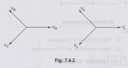
The voltages on primary and secondary sides can be represented on the phasor
diagram shown in the Fig. 7.4.1.

•
The main difficulty with this type of connection is that it can work
satisfactorily if the load is balanced. But the neutral point shifts which
makes phase voltages unequal if load is unbalanced.
•
This point can be understood properly if we consider a single phase load placed
between phase r and neutral on the secondary side. The phase R on primary side
will have to supply the power to the load. But the phase R will not supply the
necessary power as it is in series with phases Y and B whose secondaries are
open.
•
The primary coil 1 carries small current from the line as phases Y and B act as
high impedances. Thus secondary r is unable to provide necessary power. If we
consider that very small resistance is connected then very small current will
flow. Due to neutral shift the voltage Vm will reduce. But there is
increase in voltage Vyn and Vbn without affecting line
voltages on primary side. The primary phase Voltage VRN will reduced
to zero. The voltages VYN and VBN is increased to full
primary voltage.
•
This difficulty can be overcome by connecting the primary neutral to the
generator. This will make on phase R on primary side to take its power from its
line and neutral. The same effect can be observed with the connection of single
phase load between any two lines.

•
The connection of primary neutral to the neutral of generator has an added
advantage that it eliminates distortion in the secondary phase voltages. If the
flux in the core has sinusoidal waveform then it will give sinusoidal waveform
for the voltage. But due to characteristics of iron, a sinusoidal waveform of
flux requires a third harmonic component in the exciting current. As the
frequency of this component is thrice the frequency of circuit at any given
instant, it will try to flow either towards or away from the neutral point in
the transformer windings. With isolated neutral, the triple frequency current
cannot flow so the flux in the core will not be a 2 sine wave and the voltages
are distorted.
•
If primary neutral is connected to generator neutral the triple frequency
currents get the path to solve the difficulty. The alternative way of
overcoming with this difficulty is the use of tirtiary winding of low kVA
rating. These windings are s are connected in delta and provides a circuit in
which triple frequency currents can flow. Thus sinusoidal voltage on primary
will give sinusoidal voltage on ve sinusoidal voltage on secondary side.
•
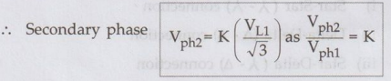
If VL1 is the line voltage is the line voltage on the primary side then phase
voltage on primary side is given

•
If K is the turns ratio or transformation ratio then phase voltage on secondary
side is given as,
Note:
Suffix 1 indicates primary side whereas suffix 2 indicates secondary side
The
line voltage VL2 on secondary side is given as,
Key Point:
The line voltage on secondary side is K times line voltage on primary side.
•
Thus in summary we can state the advantages and disadvantages of star-star
connection as follows.
a. Advantages art egribni
1.
Due to star connection, phase voltage is 1 / √3 times line voltage. Hence less
number of turns are required. Also the stress on insulation is less. This makes
the connection economical for small high voltage purposes.
2.
Due to star connection, phase current is same as line current. Hence windings
have to carry high This makes cross section of the windings high. Thus the
windings are mechanically strong and windings can bear heavy loads and short
circuit.
3.
There is no phase shift between the primary and secondary voltages.
4.
As neutral is available, it is suitable for three phase, four wire system.
b. Disadvantages
1.
If the load on the secondary side is unbalanced then the performance of this
connection is not satisfactory then the shifting of neutral point is possible.
To prevent this, star point of the primary is required to be connected to the
star point of the generator.
2.
Eventhough the star or neutral point of the primary is earthed, the third
harmonic present in the alternator voltage may appear on the secondary side.
This causes distortion in the secondary phase voltages.
Key Point :
Due to the disadvantages, this connection is rare in practice and used only for
small high voltage transformers.
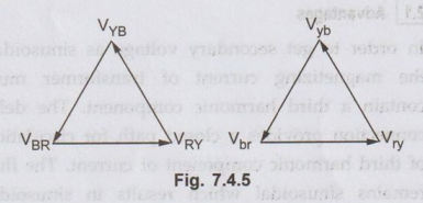
2. Delta-Delta Connection
•
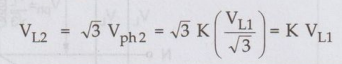
In this type of connection, both the three phase primary and secondary windings
are connected in delta as shown in the Fig. 7.4.4.
•
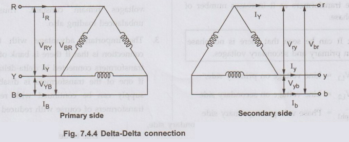
The voltages on primary and secondary sides can be shown on the phasor diagram
as shown in the Fig. 7.4.5
•
The another way of representing this type of connection is shown in the Fig.
7.4.6.

•
This connection proves to be economical for large low voltage transformers as
it increases number of turns per phase.
Key Point
It
can be seen that there is no phase shift between primary and secondary
voltages.
Let,
VL1 = Line voltage on primary side,
VL2
= Line voltage on secondary side
Vph1
= Phase voltage on primary side
Vph2
= Phase voltage on secondary side,
K
= Transformation ratio
For,
delta connection,.

But
again since secondary is connected in delta,
VL2
= Vph2 = K VL1
•
The advantages and disadvantages of this type of connection can be summerized
as follows:
a. Advantages
1.
In order to get secondary voltage as sinusoidal, the magnetizing current of
transformer must contain a third harmonic component. The delta connection
provides a closed path for circulation of third harmonic component of current.
The flux remains sinusoidal which results in sinusoidal voltages.
2.
Even if the load is unbalanced the three phase voltages remain constant. Thus
it allows unbalanced loading also.
3.
The important advantage with this type of connection is that if there is bank
of single phase transformers connected in delta-delta fashion and if one of the
transformers is disabled then the supply can be continued with remaining two
transformers of course with reduced efficiency.
4.
There is no distortion in the secondary voltages.
5.
Due to delta connection, phase voltage is same as line voltage hence windings
have more number of turns. But phase current is √3 times the current. Hence the
cross section of the windings is very less. This makes the connection
economical for low voltage transformers.
b. Disadvantage
•
Due to absence of neutral point it is not suitable for three phase four wire
system.
Key Point:
The connection is commonly used for large low voltage transformers.
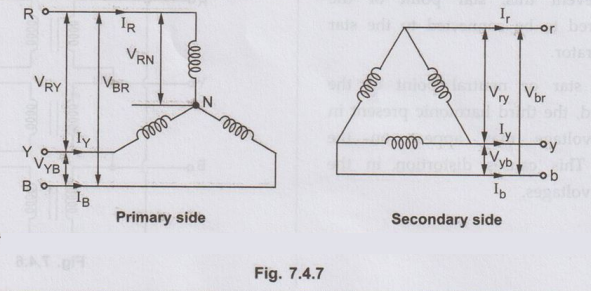
3. Star-Delta Connection
•
In this type of connection, the primary is connected in star fashion while the
secondary is connected in delta fashion as shown in the Fig. 7.4.7.
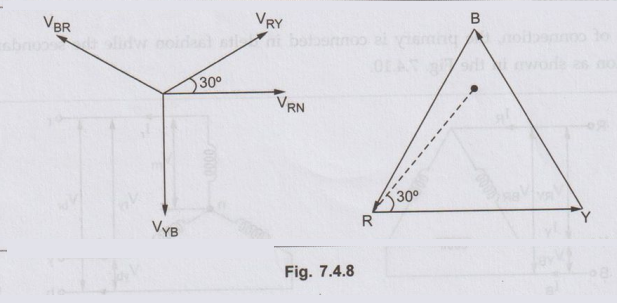
•
The voltages on primary and secondary sides can be represented on the phasor
diagram as shown in the Fig. 7.4.8.
•
The same type of connection can be represented in another way as shown in the
Fig. 7.4.9.

•
This type of connection is commonly employed at the substation end of the
transmission line. The main use with this connection is to step down the
voltage. The neutral available on the primary side is grounded. It can be seen
that there is phase difference of 30° between primary and secondary line
voltages.
Key
Point: The delta connection on secondary side allows third harmonic current to
flow which
provides
a sinusoidal flux.
Let,
VL1 = Line voltage on primary side,
VL2
= Line voltage on secondary side
Vph1
= Phase voltage on primary side
Vph2
= Phase voltage on secondary side,
K
= Transformation ratio

•
The connection suffers no problems due to unbalanced load as secondaries are
connected in delta. This type of transformers are commonly employed at
receiving end.
•
The advantages and disadvantages of this type of More connection can be stated
as follows.
a. Advantages
1.
The primary side is star connected. Hence fewer number of turns are required.
This makes the connection economical for large high voltage step down power
transformers.
2.
The neutral available on the primary can be earthed to avoid distortion.
3.
Large unbalanced loads can be handled satisfactorily.
b. Disadvantage
•
In this type of connection, the secondary voltage is not in phase with the
primary. Hence it is not possible to operate this connection in parallel with
star-star or delta-delta connected transformer.
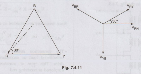
4. Delta-Star Connection
•
In this type of connection, the primary is connected in delta fashion while the
secondary is connected in star fashion as shown in the Fig. 7.4.10.

•
The voltages on primary and secondary side can be represented on the phasor
diagram as shown in the Fig. 7.4.11.
•
The another way of representing the same type of connection is shown in the
Fig. 7.4.12.
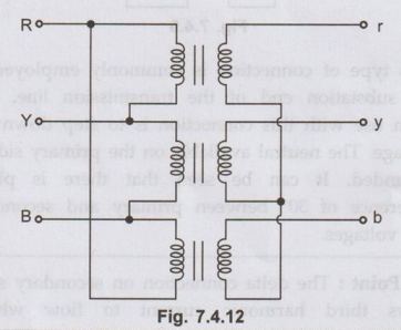
•
The main use of this connection is to step up the voltage i.e. at the begining
of high tension ed-ms transmission system. It can be noted that there is a
phase shift of 30° between primary line voltage and secondary line voltage as
leading.
Key Point:
As secondary side is star connected, use of three phase, four wire system is
possible.
•
Thus single phase and three phase loads can be supplied with this type of
connection.
So
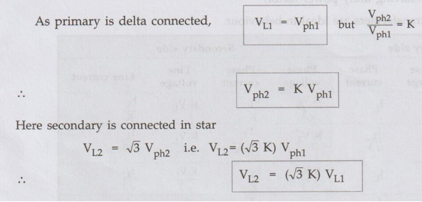
Let, VL1 = Line voltage on primary side,
VL2
= Line voltage on secondary side
Vph1
= Phase voltage on primary side
Vph2
= Phase voltage on secondary side,
K
= Transformation ratio
•
The advantages and disadvantages with this type of connection are given below.
a. Advantages
1.
On primary side due to delta connection winding cross-section required is less.
2.
On secondary side, neutral is available, due to which it can be used for 3
phase, 4 wire supply system.
3.
There is no distortion due to third harmonic components.
4.
The windings connected in star makes it economical due to saving in cost of
insulation.
5.
Large unbalanced loads can be handled without any difficulty.
b. Disadvantage
•
Due to phase shift between primary and secondary voltages, the limitation of
star-delta connection continues for this type of connection as well.
Review Question
1. With proper
connection and phasor diagrams describe the different ways of connecting three
phase transformers. AU May-04, 08, 10, 16, Dec.-04, Marks 8
Electrical Machines: Unit V: Autotransformer and Three Phase Transformer : Tag: : - Three Phase Transformer Connections
Related Topics
Related Subjects

Electrical Machines I
EE3303 EM 1 3rd Semester EEE Dept | 2021 Regulation | 3rd Semester EEE Dept 2021 Regulation