Electrical Machines II: UNIT I: a. Synchronous Generator
Three Phase Winding in A.C. Machines
Synchronous Generator
Induced e.m.f. in each set of winding is called phase e.m.f.
Three Phase Winding in A.C. Machines
In
a three phase alternators, three different sets of windings are arranged in the
armature (stator) slots in such a way that there exists a phase difference of
120° between the induced e.m.f.s in them. Each set of windings is for each
phase of three phase induced e.m.f. Thus the three phase induced e.m.f has three
different e.m.f.s given by>
eR = Em sin(rot) ... R phase
eY = Em sin(rot-120°) ... Y phase
eB = Em sin(rot-240°) ... B phase
Induced
e.m.f. in each set of winding is called phase e.m.f. denoted as Eph- All
the coils used for one phase are connected in such a way that their e.m.f.s
help each other. And overall arrangement of three phase windings is such that
the waveform of three phase induced e.m.f. is sinusoidal in nature.
1. Winding Terminologies
1)
Conductor : The part of the wire, which is under
the influence of the magnetic field and responsible for the induced e.m.f. is
called active length of the conductor. The conductors are placed in the
armature slots.
2)
Turn : A conductor in one slot, when connected to a
conductor in another slot forms a turn. So two conductors constitute a turn.
This is shown in Fig. 1.10.1 (a).

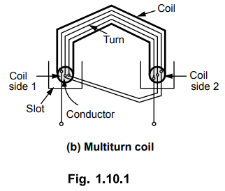
3)
Coil : As there are number of turns, for simplicity the
number of turns are grouped together to form a coil. Such a coil is called
multitum coil. A coil may consist of single turn called single turn coil. The
Fig. 1.10.1 (b) shows a multitum coil.
4)
Coil Side : Coil consists of many turns. Part of
the coil in each slot is called coil side of a coil as shown in the Fig. 1.10.1
(b).
5)
Pole Pitch : It is center to center distance between
the two adjacent poles. We have seen that for one rotation of the conductors, 2
poles are responsible for 360° electrical of e.m.f., 4 poles are responsible
for 720° electrical of e.m.f. and so on. So 1 pole is responsible for 180°
electrical of induced e.m.f. So 180° electrical is also called one pole
pitch. Practically how many slots are under one pole which are responsible for
180° electrical, are measured to specify the pole pitch.
e.g.
Consider 2 pole, 18 slots armature of an alternator. Then under 1 pole there
are 18/2 i.e. 9 slots. So pole pitch is 9 slots or 180° electrical. This means
9 slots are responsible to produce a phase difference of 180° between the
e.m.f.s induced in different conductors.
This
number of slots/pole is denoted as 'n’.
Pole
pitch = 180° electrical
=
Slots per pole (number of slots/P) = n
6)
Slot Angle (3) : The phase difference contributed by one
slot in degrees electrical is called slot angle β
As
slots per pole contributes 180° electrical which is denoted as 'ri, we can
write,
1
slot angle = 180° / n i.e. β = 180° / n
In
the above example,
n
= 18/2 = 9,
while
β = 180° / n = 20°
Note : This means that if we
consider an induced e.m.f. in the conductors which are placed in the slots
which are adjacent to each other, there will exist a phase difference of β° in
between them. While if e.m.f. induced in the conductors which are placed in
slots which are ‘n’ slots distance away, there will exist a phase difference of
180o in between them.

Review Question
1. Define turn, coil side, pole pitch and slot angle for
armature winding of an alternator.
Electrical Machines II: UNIT I: a. Synchronous Generator : Tag: Engineering Electrical Machines - II : Synchronous Generator - Three Phase Winding in A.C. Machines
Related Topics
Related Subjects

Electrical Machines II
EE3405 Machine 2 EM 2 4th Semester EEE Dept | 2021 Regulation | 4th Semester EEE Dept 2021 Regulation