Electrical Machines: Unit I: b. Electromechanical Energy Conversion
Three Phase Winding in A.C. Machines
Winding Terminologies, Types
In a three phase alternators, three different sets of windings are arranged in the armature (stator) slots in such a way that there exists a phase difference of 120° between the induced e.m.f.s in them.
Three
Phase Winding in A.C. Machines
AU : May-07, 10, Dec.-07.
• In a three phase alternators, three
different sets of windings are arranged in the armature (stator) slots in such
a way that there exists a phase difference of 120° between the induced e.m.f.s
in them. Each set of windings is for each phase of three phase induced e.m.f.
Thus the three phase induced e.m.f has three different e.m.f.s given by,
eR
= Em sin(ωt) ... R phase
eY
= Em sin(ωt-120°) ... Y phase
eB
= Em sin(ωt-240°) ... B phase
Induced e.m.f. in each set of winding is
called phase e.m.f. denoted as Eph. All the coils used for one phase
are connected in such a way that their e.m.f.s help each other. And overall
arrangement of three phase windings is such that the waveform of three phase
induced e.m.f. is sinusoidal in nature.
1. Winding Terminologies
1) Conductor :
The part of the wire, which is under the influence of the magnetic field and
responsible for the induced e.m.f. is called active length of the conductor.
The conductors are placed in the armature slots.
2) Turn : A conductor in
one slot, when connected to a conductor in another slot forms a turn. So two
conductors constitute a turn. This is shown in Fig. 2.10.1 (a)
3)
Coil : As there are number of turns, for simplicity the
number of turns are grouped together to form a coil. Such a coil is called
multiturn coil. A coil may consist of single turn called single turn coil. The
Fig. 2.10.1 (b) shows a multiturn coil.
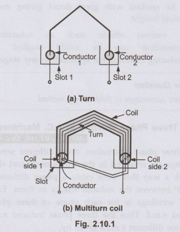
4) Coil side : Coil consists of many turns. Part of the coil in each slot is called coil side of a coil as shown in the Fig. 2.10.1 (b)
5) Pole pitch :
It is centre to centre distance between the two adjacent poles. We have seen
that for one rotation of the conductors, 2 poles are responsible for 360°
electrical of e.m.f., 4 poles are responsible for 720° electrical of e.m.f. and
so on. So 1 pole is responsible for 180° electrical of induced e.m.f. So
180° electrical is also called one pole pitch. Practically how many slots are
under one pole which are responsible for 180° electrical, are measured to
specify the pole pitch
•
e.g. Consider 2 pole, 18 slots armature of an alternator. Then under 1 pole
there are 18/2 i.e. 9 slots.
So
pole pitch is 9 slots or 180° electrical. This means 9 slots are responsible to
produce a phase difference of 180° between the e.m.f.s induced in different conductors.
•
This number of slots/pole is denoted as 'n'.
ஃ Pole
pitch = 180o electrical
=
Slots per pole (no. of slots/P) = n
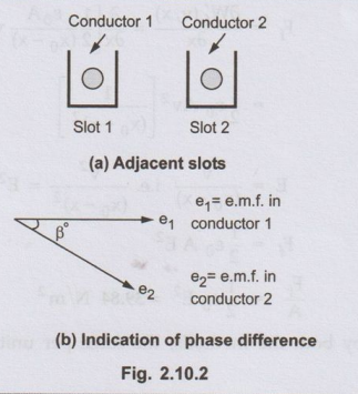
6) Slot angle (β):
The phase difference contributed by one slot in degrees electrical is called
slot angle β.
As slots per pole contributes 180° electrical
which is denoted as 'n', we can write,
ஃ 1
slot angle = 180°/n
ஃ β
= 180°/n
In
the above example,
n
= 18/2 = 9, while β = 180o = 20°
Note :
This means that if we consider an induced e.m.f. in the conductors which are
placed in the slots which are adjacent to each other, there will exist a phase
difference of β° in between them. While if e.m.f. induced in the conductors
which are placed in slots which are 'n' slots distance away, there will exist a
phase difference of 180° in between them.
2. Types of Three Phase Windings
•
In general, the types of three phase windings used in a.c. machines are,
1.
Single layer and double layer
2.
Full pitch and short pitch
3.
Concentrated and distributed.
a. Single Layer and Double Layer
Winding
•
If a slot consists of only one coil side, winding is said to be single layer.
This is shown in the Fig. 2.10.3 (a). While there are two coil sides per slot,
one at the bottom and one at the top the winding is called double layer as
shown in the Fig. 2.10.3 (b).
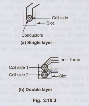
•
A lot of space gets wasted in single layer hence in practice generally double
layer winding is preferred.
b. Full Pitch and Short Pitch
Winding
•
As seen earlier, one pole pitch is 180° electrical. The value of 'n', slots per
pole indicates how many slots are contributing 180° electrical phase
difference. So if coil side in one slot is connected to a coil side in another
slot which is one pole pitch distance away from first slot, the winding is said
to be full pitch winding and coil is called full pitch coil.
•
For example in 2 pole, 18 slots alternator, the pole pitch is n = 18/2 = 9
slots. So if coil side in slot No. 1 is connected to coil side in slot No. 10
such that two slots No. 1 and No. 10 are one pole pitch or n slots or 180°
electrical apart, the coil is called full pitch coil.
•
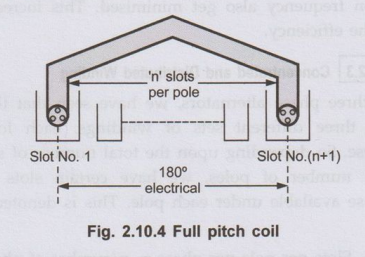
Here we can define one more term related to a coil called coil span.
Coil Span
•It
is the distance on the periphery of the armature between two coil sides of a
coil. It is usually expressed in terms of number of slots or degrees
electrical. So if coil span is 'n' slots or 180° electrical the coil is called
full pitch coil. This is shown in the Fig. 2.10.4.
•
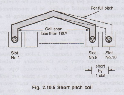
As against this if coils are used in such a way that coil span is slightly less
than a pole pitch i.e. less than 180° electrical, the coils are called, short
pitched coils or fractional pitched coils. Generally coils are shorted by
one or two slots.
•
So in 18 slots, 2 pole alternator instead of connecting a coil side in slot No.
1 to slot No.10, it is connected to a coil side in slot No.9 or slot No. 8,
coil is said to be short pitched coil and winding is called short pitch
winding. This is shown in Fig. 2.10.5.
Advantages of Short Pitch Coils
In
actual practice, short pitch coils are used as it has following advantages:
a)
The length required for the end connections of coils is less i.e. inactive
length of winding is less. So less copper is required. Hence economical.
b)
Short pitching eliminates high frequency harmonics which distort the sinusoidal
nature of e.m.f. Hence waveform of an induced e.m.f. is more sinusoidal due to
short pitching.
c)
As high frequency harmonics get eliminated, eddy current and hysteresis losses
which depend on frequency also get minimised. This increases the efficiency.
c. Concentrated and Distributed
Winding
•
In three phase alternators, we have seen that there are three different sets of
windings, each for a phase. So depending upon the total number of slots and
number of poles, we have certain slots per phase available under each pole.
This is denoted as 'm'.
m
= Slots per pole per phase = n/number of phases
n/3
(generally no. of phases is 3)
For
example in 18 slots, 2 pole alternator we have
=
18/2 = 9 and m = 9/3 = 3
•
So we have 3 slots per pole per phase available. Now let 'x' number of
conductors per phase are to be placed under one pole. And we have 3 slots per
pole per phase available. But if all 'x' conductors per phase are placed in one
slot keeping remaining 2 slots per pole per phase empty then the winding is
called concentrated winding. So in concentrated winding all conductors or
coils belonging to a phase are placed in one slot under every pole.
• But in practice, an attempt is always made
to use all the 'm' slots per pole per phase available for distribution of the
winding. So if 'x' conductors per phase are distributed amongst the 3 slots per
phase available under every pole, the winding is called distributed winding.
So in distributed type of winding all the coils belonging to a phase are well
distributed over the 'm' slots per phase, under every pole. Distributed winding
makes the waveform of the induced e.m.f. more sinusoidal in nature. Also in
concentrated winding due to large number of conductors per slot, heat
dissipation is poor.
Key Point:
So in practice, double layer, short pitched and distributed type of armature
winding is preferred for the alternators.
Review Questions
1. Explain why
distributed field winding is employed in cylindrical rotor synchronous machine.
AU: May-07, 10, Marks 6
2. What are full
chorded and short chorded coils ?
AU: Dec.-07, Marks 4
Electrical Machines: Unit I: b. Electromechanical Energy Conversion : Tag: : Winding Terminologies, Types - Three Phase Winding in A.C. Machines
Related Topics
Related Subjects

Electrical Machines I
EE3303 EM 1 3rd Semester EEE Dept | 2021 Regulation | 3rd Semester EEE Dept 2021 Regulation