Microprocessors and Microcontrollers: Unit V: (b) Introduction to RISC Based Architecture
Timer Programming
Introduction to RISC Based Architecture
• Steps for Programming PIC18F458 Timer 1. Configure the Timer Control Register. 2. Clear Timer interrupt flag. 3. Load the count in Timer register. 4. Set Timer ON bit to start the Timer operation. 5. Wait for Timer interrupt flag to become 1. Timer interrupt flag bit = 1, indicates the occurrence of the timer overflow.
Timer Programming
•
Steps for Programming PIC18F458 Timer
1.
Configure the Timer Control Register.
2.
Clear Timer interrupt flag.
3.
Load the count in Timer register.
4.
Set Timer ON bit to start the Timer operation.
5.
Wait for Timer interrupt flag to become 1. Timer interrupt flag bit = 1,
indicates the occurrence of the timer overflow.
Example
18.15.1 Write a PIC18 assembly program to generate a
square wave with period of 10 ms on pin PORTB.5. Assume XTAL = 10 MHz.
Solution:
Given: Fosc = 10 MHz, Period = 10 ms.

BCF
TRISB, 5 ; Configure PB5 as an output
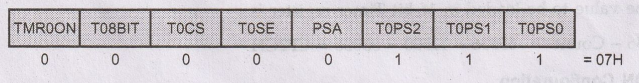
MOVLW
08H ; Timer0, 16-bit, int clk, no prescalar
MOVWF
T0COM ; Load bit pattern in T0CON register
BACK
MOVLW CFH ; W = CFH (Higher Byte)
MOVWF
TMR0H ; Load Higher byte in TMR0H
MOVLW
2CH ; W = 2CH (Lower Byte)
MOVWF
TMR0L ; Load Lower byte in TMR0L
BCF
INTCON, TMR0IF ; Clear Timer interrupt flag bit
BSF
TOCON, TMR0ON ; Start Timer0
HERE BTFSS INTCON, TMROIF BRA HERE ; Check Timer0
flag until
BRA
HERE ; it rolls over
BCF
TOCON, TMR0ON ; Stop Timer0
BTG
PORTB, 5 ; Toggle PB5
BRA
BACK ; Repeat
Example
18.15.2 Write a PIC18 assembly program to generate a
square wave of 1 Hz on pin PORTB.5. Assume XTAL = 10 MHz. Use Timer0, 16-bit
mode, with prescalar = 256.
Solution:

The
value to be loaded in 16-bit Timer register is :
65536-Count
= 65536 - 4883 = 60653 = ECEDH
TOCON
Configuration
BCF
TRISB, 5 ; Configure PB5 as an output
MOVLW
07H ; Timer0, 16-bit, int clk, prescalar
1: 256
MOVWF
TOCOM ; Load bit pattern in T0CON register
BACK MOVLW ECH ; W = ECH (Higher Byte)
MOVWF
TMR0H ; Load Higher byte in TMR0H
MOVLW
EDH ; W EDH (Lower Byte)
MOVWF
TMR0L ; Load Lower byte in TMR0L
BCF
INTCON, TMR0IF ; Clear Timer interrupt
flag bit
BSF
T0CON, TMR0ON ; Start Timer0
HERE BTFSS INTCON, TMR0IF ; Check Timer0 flag until
BRA
HERE ; it rolls over
BCF
T0CON, TMR0ON ; Stop Timer0
BTG
PORTB, 5 ; Toggle PB5
BRA
BACK ; Repeat
Example
18.15.3 Write a C18 program to toggle all bits of Port B
continuously with delay of 20 ms using Timer 0, 16 bit mode and 1:8 prescaler.
Assume XTAL = 10 MHz.
Solution:
Given: FOSC = 10 MHz. Prescaler = 1:8

#include
<P18F458.h>
Void
T0Delay(void);
{
TRISB
= 0; // configure Port B as output
While(1)
{
PORTB
= 0x55; // Load bit patterns
T0Delay
();
PORTB
= 0xAA;
T0Delay
();
}
}
void
T0Delay ( )
{
T0CON=0x02; // Timer0, 16 bit mode, 1:8 prescaler
TMR0H=0xE7; // Load Higher byte in TMROH
TMR0L=
0x96; // Load Lower byte in TMR0L
T0CONbits.TMR0ON=1; // Start the Timer0
while(INTCONbits.
TMR0IF==0); // Check for overflow
T0CONbits.TMR0ON=0; // Turn off Timer0
INTCONbits.TMR0IF==0; // Clear the Timer0 interrupt flag
}
Example
18.15.4 Write a C18 program to toggle only the RC5 bit
continuously every 50 ms using Timer 0, 16 bit mode and 1: 4 prescaler. Assume
XTAL = 10 MHz.
Solution:
Given: FOSC = 10 MHz. Prescaler =
1 : 4

#define
PORTBit PORTCbits.RC5
void
main(void)
{
TRISCbits.TRISC5=0; // configure pin 5 of Port C as output
while(1)
{
PORTBit
^ = 1; // Toggle the bit RC5
T0Delay
(); // Wait for 50 ms
}
}
void
T0Delay ()
{
T0CON=0x01; // Timer0, 16 bit mode, 1:4 prescaler
TMR0H=0x85; // Load Higher byte in TMR0H
TMR0L=
0xEE; // Load Lower byte in TMR0L
T0CONbits.
TMR0ON=1; // Start the Timer0
while(INTCONbits.
TMR0IF==0); // Check for overflow
T0CONbits.TMR0ON=0; // Turn off Timer0
INTCONbits.TMR0IF==0; // Clear the Timer0 interrupt flag
}
Example
18.15.5 Write a C18 program to toggle only the RB4 bit
continuously every 10 ms using Timer0, 8-bit mode. Assume XTAL = 10 MHz.
Solution:
Given: FOSC = 10 MHz. Assume: Prescaler = 1 : 1
FTIMER
= FOSC / 4 × Prescaler ratio
= 10 / 4 1 × 1 / 1 = 2.5 MHz
Period
= 1 / FTIMER = 1 / 2.5 MHz = 0.4 μs
Count
= Desired Delay / Timer Period = 10 ms / 0.4 µs = 25000
For
8-bit timer, prescaler ratio > = 25000/256 = 97.66
ஃ Prescaler = 1 : 128
Count
(with Prescaler = 1 : 128) 1: 128) = 25000/128 25000/128 = 195.3125 ≈ 195
The
value to be loaded in 8-bit Timer register is :
256
- Count = 256 - 195 = 61 3DH
T0CON
Configuration

#include
<P18F458.h>
void
T0Delay(void);
#define
PORTBit PORTBbits.RB4
void
main(void)
{
TRISBbits.TRISB4=0; // configure pin 4 of Port B as output
while(1)
{
PORTBit
^ = 1; // Toggle the bit RB4
T0Delay(); // Wait for 10 ms
}
}
void
TODelay ( )
{
T0CON=0x46; // Timer0, 8 bit mode, 1:128 prescaler
TMR0L=
0x3D; // Load byte in TMROL
TOCONbits.TMR0ON=1; // Start the Timer0
while(INTCONbits.
TMR0IF==0); // Check for overflow
T0CONbits.TMR0ON=0; // Turn off Timer0
INTCONbits.TMR0IF==0; // Clear the Timero interrupt flag
}
Note:
When
maximum prescalar count is not sufficient to produce desired delay we can
call Delay subroutine multiple times. See following example.
Example
18.15.6 Write a C18 program to toggle only the RB4 bit
continuously every 100 ms using Timer0, 8-bit mode. Assume XTAL = 10 MHz.
Solution:
Given: FOSC = 10 MHz. Assume: Prescaler = 1:1
FTIMER
= FOSC / 4 × Prescaler ratio = 10/4 × 1/1 = 2.5 MHz
Period
= 1 / FTIMER = 1 / 2.5 MHz = 0.4 µs
Count
= Desired Delay / Timer Period = 100 ms / 0.4 µs = 250000
For
8-bit timer, prescaler ratio >= 250000 / 256 = 970.66
Here,
we choose maximum prescaler
ஃ
Prescaler
= 1: 256
Thus,
the delay subroutine must be called 4 times so that 4 × 256 > 970.66.
Count
(with Prescaler = 1: 256) = 250000/(256 × 4) = 244.14 = 244
The
value to be loaded in 8-bit Timer register is :
256
- Count = 256 - 244 = 12 = 0CH
T0CON
Configuration

#include
<P18F458.h>
void
T0Delay(void);
#define
PORTBit PORTBbits.RB4
void
main(void)
{
TRISBbits.TRISB4=0; // configure pin 4 of Port B as output
while(1)
{
PORTBit
^ = 1; // Toggle the bit RB4
for
(i = 0; i < 4; i++)
T0Delay(); // Wait for 25 ms
}
}
void
T0Delay()
{
T0CON=0x47;
// Timer0, 8 bit mode, 1:256 prescaler
TMR0L=
0x0C; // Load byte in TMR0L
T0CONbits.TMR0ON=1;
// Start the Timer0
while(INTCONbits.TMR0IF==0);
// Check for overflow
T0CONbits.TMR0ON=0; // Turn off Timero
INTCONbits.TMR0IF==0; // Clear the Timero interrupt flag
}
Actual
Delay :
FTIMER
= FOSC / 4 × Prescaler ratio = 10 / 4 × = 9.765625 KHz
Period
= 1 / FTIMER = 1 / 9.765625 KHz = 102.4 µs
Delay
subroutine execution time = 244 × 102.4 µs = 24.9856 ms
Since
delay subroutine is called 4 times we get delay of 99.9424 ms
Example
18.15.7 Write a C18 program to create frequency of 5KHz
on pin RC5 using Timer1. Assume XTAL 10 MHz.
Solution:
Given: FOSC = 10 MHz. No Prescaler

The
value to be loaded in 16-bit Timer register is :
65536-Count
= 65536 - 250 = 65286 = FF06H
#include
<P18F458.h>
void
T1Delay(void);
#define
PORTBit PORTCbits.RC5
void
main(void)
{
TRISCbits.TRISC5=0; // configure pin 5 of Port C as output
while(1)
{
PORTBit
^ = 1; // Toggle the bit RC5
T1Delay
(); // Wait for 50 ms
}
}
void
T1Delay()
{
T1CON=0x00; // Timer1, 16 bit mode, no prescaler
TMR1H=0xFF; // Load Higher byte in TMR1H
TMR1L=
0x06; // Load Lower byte in TMR1L
T1CONbits.TMR1ON=1 // Start the Timer1
;
while(PIR1bits.TMR1IF==0); // Check for
overflow
T1CONbits.TMR1ON=0; // Turn off Timer1
PIR1bits.TMR1IF==0; // Clear the Timer1 interrupt flag
}
Example
18.15.8 Write a program to generate 100 msec delay using
Timer1. What are the values to be loaded in T1CON, TMR1H, and TMR1L. Assume
XTAL = 8 MHz.
Solution:
Given: FOSC = 8 MHz. Assume: Prescaler = 1 : 4
FTIMER
= FOSC / 4 × Prescaler ratio = 8 / 1 × 1 / 4 = 500 KHz
Period
= 1 / FTIMER = 1 / 500 KHz =
2 µs
Count
= Desired Delay / Timer Period = 2 µs = 50000
The
value to be loaded in 16-bit Timer register is :
65536
- Count = 65536-50000 = 15536= 3CB0H
#include
<P18F458.h>
void
T1Delay(void);
void
T1Delay ()
{
T1CON=0x20;
// Timer1, 16 bit mode, 1 : 4 prescaler
TMR1H=0x3C;
// Load Higher byte in TMR1H
TMR1L=
0xB0; // Load Lower byte in TMR1L
T1CONbits.
TMR1ON=1; // Start the Timer1
while(PIR1bits.TMR1IF==0);
// Check for overflow
T1CONbits.TMR1ON=0; // Turn off Timer1
PIR1bits.TMR1IF==0; // Clear the Timer1 interrupt flag
Microprocessors and Microcontrollers: Unit V: (b) Introduction to RISC Based Architecture : Tag: : Introduction to RISC Based Architecture - Timer Programming