Microprocessors and Microcontrollers: Unit II: (b) Looping, Counting, Time Delays & Code Conversion
Timers
using NOP Instruction - Counters - Nested Loops
Questions : 1. Write a program to count from 0 to 9 with one second delay between each count. At the count of 9, the counter should reset itself to 0 and repeat the sequence continuously. Assume the clock 2. Explain the need of software timers. 3. Explain how software delays can be implemented using counters.
Timers
In
the real time applications, such as traffic light control, digital clock,
process control, serial communication, it is important to keep a track with
time. For example in traffic light control application, it is necessary to give
time delays between two transitions. These time delays are in few seconds and
can be generated with the help of executing group of instructions number of
times. This software timers are also called time delays or software delays.
To
execute instructions, microprocessor takes fix time as per the instruction,
since it is driven by constant frequency clock. This makes it possible to
introduce delay for specific time between two events. In the following section
we will see different delay implementation techniques.
1. Timer Delay using NOP Instruction
NOP
instruction does nothing but takes 4T states of processor time to execute. So
by executing NOP instruction in between two instructions we can get delay of 4
T-state
1
T state = 1/Operating frequency of 8085
2. Timer Delay using Counters
Counting
can create time delays. Since the execution times of the instructions used in a
counting routine are known, the initial value of the counter, required to get
specific time delay can be determined.
Using
8-bit counter :
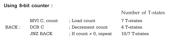
In
this program, the instructions DCR C and JNZ BACK execute number of times equal
to count stored in the C register. The time taken by this program for execution
can be calculated with the help of T-states. The column to the right of the
comments indicates the number of T-states in the instruction cycle of each
instruction. Two values are specified for the number of T-states for the JNZ
instruction. The smaller value is applied when the condition is not met, and
the larger value applied when it is met. The first instruction MVI C, count
executed only once and it requires 7 T-states. There are count - 1 passes
through the loop where the condition is met and control is transferred back to
the first instruction in the loop (DCR C). The number of T-states that elapse
while C is not zero are (count -1) × (4+10). On the last pass through the loop,
the condition is not met and the loop is terminated. The number of T states
that elapse in this pass are 4 + 7.
Total
T-states required to execute the given program
=
7 + (count -1) × (4 + 10 ) + (4 + 7)
MVI C
Loops Last loop
For
count = 5
Number
of T-state = X + (5 -1) × (14) + (11) = 7 + 56 + 11 = 74
Assuming
operating frequency of 8085A is 2 MHz,
Time
required for 1 T-state = 1/2 MHz = 0.5 µsec
Total
time required to execute the given program = 74 × 0.5 µsec. = 37 µsec.
Maximum
delay possible with 8-bit count
The
maximum count that can be loaded in the 8 bit register is FFH (255) so the
maximum delay possible with 8 bit count, assuming operating frequency 2 MHz
=
(7 + (255 - 1) × (14) + (11)) x 0.5
µsec. = 1787 µsec.
With
these calculations, it can be noticed that delay with 8 bit count suitable for
small delays and not for large delays.
Using
16-bit counter :
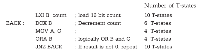
In
this program, the instructions DCX B, MOV A, C, ORA B and JNZ BACK execute
number of times equal to count stored in BC register pair. The instruction LXI
B, count is executed only once. It requires 10 T-states. The number of T-states
required for one loop = 6 + 4 + 4 + 10 = 24 T-states. The number of T-states
required for last loop = 6 + 4 + 4 + 7 = 21 T-states. So total T-states required
for execution of given program are
=
10 + (count-1) × 24 + 21
LXI B
Loops Last loop
for
count = 03FFH(102310)
Number
of T-states = 10 + (1022) × 24 + 21
=
24559
Assuming
operating frequency of 8085A as 2 MHz, the time required for,
T
state = 0.5 µsec
Total
time required to execute the given program
=
24559 × 0.5 µsec
=
12279.5 , µsec
=
12.2795 msec
Maximum
delay possible with 16-bit count
The
maximum count that can be loaded in the 16 bit register pair is (65535
H).
So
the maximum delay possible with 8 bit count, assuming operating frequency 2
MHz.
=
10(10 + (65535 - 1) × (24) + (21)) x 0.5
µsec
=
0.786425 sec
If
the application requires the delays more than this, then the nested loop
technique is used to implement the delays.
3. Timer Delay using Nested Loops
In
this, there are more than one loops. The innermost loop is same as explained
above. The outer loop sets the multiplying count to the delays provided by the
innermost loop.
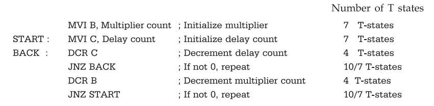
T-states
required for execution of inner loop
Tinner
= 7 + (Delay count - 1 ) × 14 + 11
T-states
required for execution of the given program
=
(Multiplier count - 1) × (T inner +14) + 11
For
delay count = 65H (101) and multiplier count
=
51H (81)
Tinner
= 7 + (101-l) × 14 + 11
=
1418
Total
time required to execute the given program is
(Operating
frequency is X MHz) = [(81-1) × (1418 + 14) +11] × 0.5 µsec.
=
57.2855 msec.
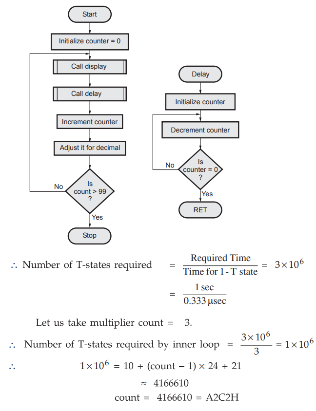
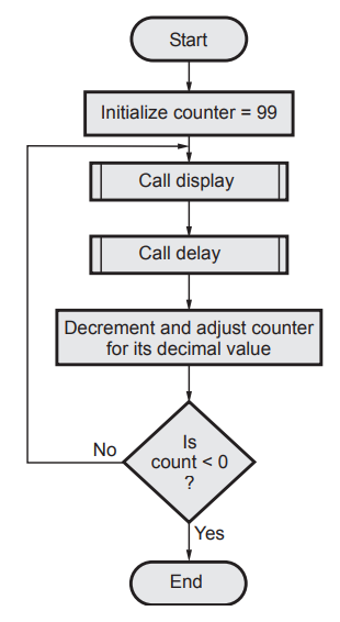
Lab Experiment 3.2.1 : Generate a delay
of 0.4 seconds.
Statement :
Write a program to generate a delay of 0.4 sec if the crystal frequency is 5
MHz.
Solution
:
In 8085, the operating frequency is half of the crystal frequency,
Operating
frequency = 5/2 = 2.5 MHz
Time
for one T-state = 1/2.5 MHz = 0.4 µsec
Number
of T-states required = Required Time / Time for 1T – state = 0.4 sec / 0.4 µsec
=
1 × 10⁶
Delay
program :
LXI
B, count ; 16-bit count
BACK
: DCX B ; Decrement count
MOV
A, C
ORA
B ; Logically OR B and C
JNZ
BACK ; If result is not zero repeat
1
× 106 = 10 + (count - 1) × 24 + 21
count
= (1 × 10⁶ – 31 / 24) + 1 ≈ 4166610
count
= 4166610 = A2C2H
Lab Experiment 3.2.2 : Generate and
display binary up counter.
Statement :
Write a program for displaying binary up counter. Counter should count numbers
from 00 to FFH and it should increment after every 0.5 sec.
Assume
operating frequency of 8085 equal to 2 MHz. Display routine is available.
Solution
:
LXI
SP, 27FFH ; Initialize stack pointer
MVI
C, OOH ; Initialize counter
BACK
: CALL Display ; Call display subroutine
CALL
Delay ; Call delay subroutine
INR
C ; Increment counter
MOV
A, C
CPI
00 ; Check counter is > FFH
JNZ
BACK ; If not, repeat
HLT
; Stop
Delay
subroutine :
Delay
: LXI D, count ; Initialize count
BACK
: DCXD ; Decrement count
MOV
A, E
ORA
D ; Logically OR D and E
JNZ
BACK; If result is not 0 repeat
RET
; Return to main program
Flowchart
:

Lab Experiment 3.2.3 : Generate and
display BCD up counter with frequency 1 Hz.
Statement :
Write a program for displaying BCD up counter. Counter should count numbers
from 00 to 99H and it should increment after every 1 sec. Assume operating
frequency of 8085 equal to 3 MHz. Display routine is available.
Solution
:
LXI
SP, 27 FFH ; Initialize stack pointer
MVO
C, 00H ; Initialize counter
BACK
: CALL Display ; Call display subroutine
CALL
Delay ; Call delay subroutine
MOV
A, C ;
ADI
, 01 ; Increment counter
DAA
; Adjust it for decimal
MOV
C, A ; Store count
CPI,
00 ; Check count is > 99
JNZ
BACK ; If not, repeat
HLT
; Stop
Delay
subroutine :
Delay
: MVI B, Multiplier-count; Initialize multiplier count
BACK1:
LXI D, Initialize Count
BACK
: DCX D ; Decrement count
MOV
A, E ;
ORA
D ; Locally OR D and E
JNZ
BACK ; If result is not 0, repeat
DCR
B ; Decrement multiplier count
JNZ
BACK1 ; If not zero, repeat
RET
; Return to main program.
Operating
frequency : 3 MHz
Time
for one T-state = 1/ 3MHz = 0.333 µsec
Flowchart
:
Lab Experiment 3.2.4 : Generate and
display BCD down counter with frequency 1 Hz
Statement :
Write a program for displaying BCD down counter. Counter should count numbers
from 99 to 00 and it should decrement after every 1 sec. Assume display and
delay routines are available.
Solution
: Flowchart :
Source
program wioth logic 1 :
LXI
SP, 27 FFH ; Initialize stack pointer
MVI
C, 99H ; Initialize counter
BACK
: CALL Display ; Call display subroutine
CALL
Dealy ; Call delay subroutine
ADI
99H ; * (Explain later)
DAA
; Adjust for decimal
CPI
99H ; Compare with last count
JNZ
BACK ; If no, repeat
*Addition
:
Program
with logic 2 :
LXI
SP, 27FFH ; Initialize stack pointer
MVI
C, 99H ; Initialize counter = 99
BACK
: Call Display ; Call display subroutine
Call
Delay ; Call Delay subroutine
MOV
A, C ; Get the count
ANI
0FH ; Check for lower nibble
JNZ
SKIP ; If it is not 0FH go to skip
MOV
A, C ; Else get the count
SBI
06 ; and subtract 6
MOV
C, A ; Store the count
SKIP
: DCR C ; Decrement count
MOV
A, C ; Get the count
CPI
99H ; Check it for last count
JNZ
BACK ; If not, repeat
HLT
; Stop
Review Questions
1. Write a program to
count from 0 to 9 with one second delay between each count. At the count of 9,
the counter should reset itself to 0 and repeat the sequence continuously.
Assume the clock
AU : Dec.-11, Marks 8
2. Explain the need of
software timers.
3. Explain how software delays can be implemented using counters.
Microprocessors and Microcontrollers: Unit II: (b) Looping, Counting, Time Delays & Code Conversion : Tag: : using NOP Instruction - Counters - Nested Loops - Timers
Related Topics
Related Subjects
Microprocessor and Microcontroller
EE3404 MCU 4th Semester EEE Dept | 2021 Regulation | 4th Semester EEE Dept 2021 Regulation