Electrical Machines II: UNIT III: a. Three Phase Induction Motor
Torque Equation
Three Phase Induction Motor
The torque produced in the induction motor depends on the following factors. 1. The part of rotating magnetic field which reacts with rotor and is responsible to produce induced e.m.f. in rotor. 2. The magnitude of rotor current in running condition. 3. The power factor of the rotor circuit in running condition.
Torque Equation
The
torque produced in the induction motor depends on the following factors.
1.
The part of rotating magnetic field which reacts with rotor and is responsible
to produce induced e.m.f. in rotor.
2.
The magnitude of rotor current in running condition.
3.
The power factor of the rotor circuit in running condition.
Mathematically
the relationship can be expressed as,
T
∝ ϕ I2r cos ϕ2r ...(5.9.1)
where ϕ = Flux responsible to produce
induced e.m.f.
I2r
- Rotor running current
cos
ϕ2r = Running p.f. of rotor
The
flux ϕ produced by stator is proportional to E1i.e. stator voltage.
ϕ
∝ E1 ... (5.9.2)
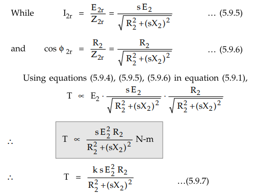
While
E1 and E2 are related to each
other through ratio of stator turns to rotor turns i. e. K.
E2 / E1 = K ... (5.9.3)
Using
equation (5.9.3) in equation (5.9.2) we can write,
E2 ∝
ϕ
... (5.9.4)
Thus
in equation (5.9.1), ϕ can be replaced by E2.
where
K = Constant of proportionality
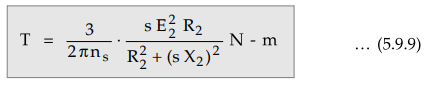
The
constant k is proved to be 3/2πns for the three phase induction
motor.
k
= 3/2πns
Key
Point nS = Synchronous speed in r.p.s. = NS/60
Using
equation (5.9.8) in equation (5.9.7) we get the torque equation as,
So
torque developed at any load condition can be obtained if slip at that load is
known and all standstill rotor parameters are known.
1. Starting Torque
Starting
torque is nothing but the torque produced by an induction motor at start. At
start, N = 0 and slip s = 1. So putting s = 1 in the torque equation we can
write expression for the starting torque Tst as,
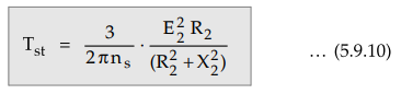
Key Point From the equation
(5.9.10), it is clear that by changing R2 the starting torque Tst can be
controlled.
The
change in R2 at start is possible in case of slip ring induction
motor only. This is the principle used in case of slip induction motor to control
the starting torque Tst.
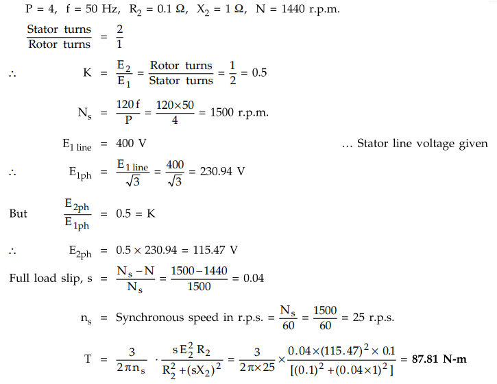
Example
5.9.1 A 3 phase, 400 V, 50 Hz, 4 pole induction motor
has star connected stator winding. The rotor resistance and reactance are 0.1 Q
and 1 Q respectively. The full load speed is 1440 r.p.m. Calculate the torque
developed on full load by the motor. Assume stator to rotor ratio as 2 : 1.
Solution
:
The given values are,
Example
for Practice
Example
5.9.2 A 4 pole, 50 Hz, 3-ϕ, IM has a rotor resistance
of 4.5 Q / phase and standstill reactance of 8.5 Ω / phase. With no external
resistance in the rotor circuit, the starting torque of the motor is 85 N-m.
i)
What is the rotor voltage at standstill ?
ii)
What would be the starting torque if 3 Ω resitance were added in each rotor
phase ?
iii)
Neglecting stator voltage drop, what would be the induced rotor voltage and the
torque at a slip of 0.03 ?
[Ans.:
i) 302.46 V/ph, ii) 101.975 Nm, iii) 9.0738 V, T = 11.61 Nm]
Review Question
1. Derive the torque equation for a three phase induction motor.
AU : May-04, 11, Marks 8, May-16, Dec.-17, Marks 4
Electrical Machines II: UNIT III: a. Three Phase Induction Motor : Tag: Engineering Electrical Machines - II : Three Phase Induction Motor - Torque Equation
Related Topics
Related Subjects

Electrical Machines II
EE3405 Machine 2 EM 2 4th Semester EEE Dept | 2021 Regulation | 4th Semester EEE Dept 2021 Regulation