Electrical Machines II: UNIT III: a. Three Phase Induction Motor
Torque-Slip Characteristics
Three Phase Induction Motor
As the induction motor is loaded from no load to full load, its speed decreases hence slip increases.
Torque-Slip Characteristics AU
: May-04, 13, 14, 16, 17, Dec.-05, 06, 07, 11, 12, 14, 15, 16
As
the induction motor is loaded from no load to full load, its speed decreases
hence slip increases. Due to the increased load, motor has to produce more
torque to satisfy load demand. The torque ultimately depends on slip as
explained earlier. The behaviour of motor can be easily judged by sketching a
curve obtained by plotting torque produced against slip of induction motor. The
curve obtained by plotting torque against slip from s = 1 (at start) to
s
= 0 (at synchronous speed) is called torque-slip characteristics of the
induction motor. It is very interesting to study the nature of torque-slip
characteristics.
We
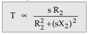
have seen that for a constant supply voltage, E2 is also constant.
So we can write torque equation as,
Now
to judge the nature of torque-slip characteristics let us divide the slip range
(s = 0 to s = 1) into two parts and analyze them independently.
i)
Low slip region :
In
low slip region, 's' is very very small. Due to this, the term (s X2)2
is so small as
compared
to R22 that it can be neglected.
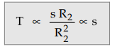 ...As R2 is constant.
Hence
in low slip region torque is directly proportional to slip. So as
load increases, speed decreases, increasing the slip. This increases the torque
which satisfies the load demand.
Hence
the graph is straight line in nature.
At
N = Ns , s = 0 hence T = 0. As no torque is generated at N - Ns,
motor stops if it tries to achieve the synchronous speed. Torque increases
linearly in this region, of low slip values.
ii)
High slip region :
In
this region, slip is high i.e. slip value is approaching to 1. Here it can be
assumed that the term R2 is very very small as compared to (s X2)2.
Hence neglecting R22 from the denominator, we get
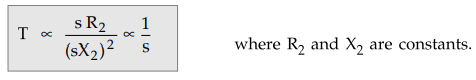
So
in high slip region torque is inversely proportional to the slip. Hence its
nature is like rectangular hyperbola.
Now
when load increases, load demand increases but speed decreases. As speed
decreases, slip increases. In high slip region as T ∝ 1/s, torque decreases
as slip increases. But torque must increase to satisfy the load demand. As
torque decreases, due to extra loading effect, speed further decreases and slip
further increases. Again torque decreases as T ∝ 1/s hence same load acts as an extra
load due to reduction in torque produced. Hence speed further drops. Eventually
motor comes to standstill condition. The motor cannot continue to rotate at
any point in this high slip region. Hence this region is called unstable
region of operation.
So
torque - slip characteristics has two parts,
1.
Straight line called stable region of operation.
2.
Rectangular hyperbola called unstable region of operation.
Now
the obvious question is upto which value of slip, torque-slip characteristic
represents stable operation ?
In
low slip region, as load increases, slip increases and torque also increases
linearly. Every motor has its own limit to produce a torque. The maximum
torque, the motor can produce as load increases is Tm which occurs at s = sm.
So linear behaviour continues till s = sm.
If
load is increased beyond this limit, motor slip acts dominantly pushing motor
into high slip region. Due to unstable conditions, motor comes to standstill
condition at such a load. Hence Tm i.e. maximum torque which motor can produce
is also called breakdown torque or pull out torque. So range s = 0 to s = sm is
called low slip region, known as stable region of operation. Motor always
operates at a point in this region. And range s = sm to s = 1 is called high
slip region which is rectangular hyperbola, called unstable region of
operation. Motor cannot continue to rotate at any point in this region.
At
s = 1, N = 0 i.e. at start, motor produces a torque called starting torque
denoted as Tst.
The
entire torque-slip characteristics is shown in the Fig. 5.11.1.

1. Full Load Torque
When
the load on the motor increases, the torque produced increases as speed
decreases and slip increases. The increased torque demand is satisfied by
drawing more current from the supply.
The
load which motor can drive safely while operating continuously and due to such
load, the current drawn is also within safe limits is called full load
condition of motor. When current increases, due to heat produced the temperature
rises. The safe limit of current is that which when drawn for continuous
operation of motor, produces a temperature rise well within the limits. Such a
full load point is shown on the torque-slip characteristics as point C in the
Fig. 5.11.1 and corresponding torque as TF.L.
The
interesting thing is that the load on the motor can be increased beyond point C
till maximum torque condition. But due to high current and hence high
temperature rise there is possibility of damage of winding insulation, if motor
is operated for longer time duration in this region i.e. from point C to B.
But motor can be used to drive loads more than full load, producing torque upto
maximum torque for short duration of time. Generally full load torque is less
than the maximum torque.
So
region OC upto full load condition allow motor operation continuously and
safely from the temperature point of view. While region CB is possible to
achieve in practice but only for short duration of time and not for continuous
operation of motor. This is the difference between full load torque and the
maximum or breakdown torque. The breakdown torque is also called stalling
torque.
TFull
load < Tm
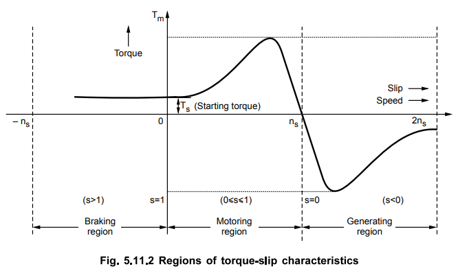
2. Generating and Braking Region
When
the slip lies in the region 0 and 1 i.e. when 0 ≤ s ≤ 1, the machine runs as a
motor which is the normal operation. The rotation of rotor is in the direction
of rotating field which is developed by stator currents. In this region it
takes electrical power from supply lines and supplies mechanical power output.
The rotor speed and corresponding torque are in same direction.
When
the slip is greater than 1, the machine works in braking mode. The motor is
rotated in opposite direction to that of rotating field. In practice two of the
stator terminals are interchanged which changes the phase sequence which in
turn reverses the direction of rotation of magnetic field. The motor comes to
quick stop under the influence of counter torque which produces braking action.
This method by which the motor comes to rest is known as plugging. Only care is
taken that the stator must be disconnected from the supply to avoid the rotor
to rotate in other direction.
To
run the induction machine as a generator, its slip must be less than zero i.e.
negative. The negative slip indicates that the rotor is running at a speed
above the synchronous speed. When running as a generator it takes mechanical
energy and supplies electrical energy from the stator.
Thus
the negative slip, generating action takes place and nature of torque-slip
characteristics reverses in this generating region.
The
Fig. 5.11.2 shows the complete torque-slip characteristics showing motoring,
generating and the braking region.
Review Questions
1. Draw and explain a typical torque-speed characteristics for a
3 phase induction motor. Explain the relation between torque and slip before
and after the maximum toruque. Show the stable region in the graph.
2. Discuss the complete torque-slip characteristics of a three
phase induction motor including motoring, generating and braking regions.
Electrical Machines II: UNIT III: a. Three Phase Induction Motor : Tag: Engineering Electrical Machines - II : Three Phase Induction Motor - Torque-Slip Characteristics
Related Topics
Related Subjects

Electrical Machines II
EE3405 Machine 2 EM 2 4th Semester EEE Dept | 2021 Regulation | 4th Semester EEE Dept 2021 Regulation