Electrical Machines: Unit IV: Single Phase Transformer
Transformer on Load (M.M.F. Balancing on Load)
Single Phase Transformer
When the transformer is loaded, the current I2 flows through the secondary winding. The magnitude and phase of I2 is determined by the load. If load is inductive, I2 lags V2. If load is capacitive, I2 leads V2 while for resistive load, I2 is in phase with V2.
Transformer
on Load (M.M.F. Balancing on Load )
AU May-08, Dec.-14
•
When the transformer is loaded, the current I2 flows through the
secondary winding. The magnitude and phase of I2 is determined by
the load. If load is inductive, I2 lags V2. If load is
capacitive, I2 leads V2 while for resistive load, I2
is in phase with V2.
• There exists a secondary m.m.f. N2
I2 due to which secondary current sets up its own flux ϕ2.
This flux ϕ opposes the main flux which is produced in the core due to
magnetising component of no load current. Hence the m.m.f. N2I2
is called demagnetising ampere-turns. This is shown in the Fig. 6.8.1 (a).

•
The flux ϕ2 momentarily reduces the main flux ϕ, due to which the
primary induced e.m.f. E1 also reduces. Hence the vector difference ????
increases due to which primary draws more current from the supply. This
additional current drawn by primary is due to the load hence called load
component of primary current denoted as 1'2 as shown in the Fig.
6.8.1 (b).
•
This current I'2 is in antiphase with 12. The current I'2
sets up its own flux ϕ'2 which opposes the flux ϕ2 and
helps the main flux ϕ This flux ϕ'2 neutralises the flux I2
produced by 12. The m.m.f. i.e. ampere turns N1 I'2
balances the ampere turns N2I2. Hence the net flux in the
core is again maintained at constant level.
Key Point:
Thus for any load condition, no load to full load the flux in the core is
practically constant.
•
The load component current I'2 always neutralises the changes in the
load. As practically flux in core is constant, the core loss is also constant
for all the loads. Hence the transformer is called constant flux machine.
As
the ampere turns are balanced we can write, N2 I2 = N1
1'2
I'2
= N2 / N1 I2 = K I2 (6.8.1)
•
Thus when transformer is loaded, the primary current I1 has two
components:
1.
The no load current I0 which lags V1 by angle ϕ0.
It has two components Im and
Ic.
2.
The load component I'2 which is in antiphase with I2. And
phase of I2 is decided by the load.
Hence
primary current I1 is vector sum of I0 and I'2.

•
Assume inductive load, I2 lags E2 by ϕ2, the
phasor diagram is shown in the Fig. 6.8.2 (a).
•
Assume purely resistive load, I2 in phase with E2, the
phasor diagram is shown in the Fig. 6.8.2 (b).
•
Assume capacitive load, I2 leads E2 by ϕ2, the
phasor diagram is shown in the Fig. 6.8.2 (c).

Note
that I'2 is always in antiphase with I2.
Actually
the phase of I2 is with respect to V2 i.e. angle ϕ2
is angle between I2 and V2. For the ideal case, E2
is assumed equal to V2 neglecting various drops.
The
current ratio can be verified from this discussion. As the no load current I0
is very small, neglecting I0 we can write, I1 = I'2
Balancing
the ampere-turns, N1 I'2 = N1 I1 =
N2 I2
N2
/N1= I1 /I2= K
Under
full load conditions when I0 is very small compared to full load
currents, the ratio of primary and secondary current is constant.
Ex. 6.8.1
A single phase transformer takes 10 A on
no-load at 0.2 p.f. lagging. The turns ratio is 4: 1 (step down). If the load
on the secondary is 200 A at a p.f. of 0.85 lagging, find the primary current
and power factor. Neglect the voltage drop in the winding. Also draw the phasor
diagram. AU May-08, Marks 8
Sol:
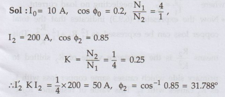
I2
is in antiphase with I2 which lags E2 by 31.788°.
The
phasor diagram is shown in the Fig. 6.8.3 (a) with flux ϕ as the reference.
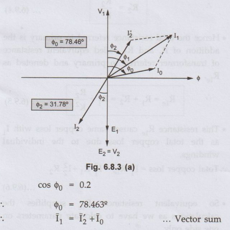
Resolve
I2 and I0 into two components, along and in quadrature
with ϕ
Horizontal
component of I0 = I0 sin ϕ0 = 9.798
Vertical
component of I0 = I0 cos ϕ0 = 2
Horizontal
component of I2 = I2 sin ϕ2 = 26.3388

Review Questions
1. Explain the
behaviour of transformer on load. AU: Dec.-14, Marks 8
2. A 400/200 V
transformer takes 1 A at a power factor of 0.4 on no load. If the secondary
supplies a load current of 50 A at 0.8 lagging power factor, calculate the
primary current.
[Ans. : I1
= 25.874 A, cos ϕ1 = 0.788 lagging]
3. Explain how the
flux in the transformer core remains fairly constant from no load to full load
assuming lagging power factor.
4. A 400/200 V,
single-phase transformer supplies a load of 50 amps at 0.866 p.f. lagging. The
no-load primary current is 2 amp at 0.208 p.f. lagging. Calculate the primary
current and primary power factor. Draw the relevant phasor diagram.
[Ans. I1 = 26.38 A, cos ϕ1
= 0.8364 lag]
Electrical Machines: Unit IV: Single Phase Transformer : Tag: : Single Phase Transformer - Transformer on Load (M.M.F. Balancing on Load)
Related Topics
Related Subjects

Electrical Machines I
EE3303 EM 1 3rd Semester EEE Dept | 2021 Regulation | 3rd Semester EEE Dept 2021 Regulation