Linear Integrated Circuits: Unit III: Applications of Op-amp
Triangular Wave Generator using Op-amp
Working Principle, Pulse, Circuit Diagram, Amplitude and Frequency Calculations, Solved Example Problems | Operational amplifier
We have seen that, the output of integrator is a triangular wave if its input is a square wave. This means that a triangular wave generator can be formed by simply connecting an integrator to the square wave generator as shown in the Fig. 3.20.1.
Triangular Wave Generator
We
have seen that, the output of integrator is a triangular wave if its input is a
square wave. This means that a triangular wave generator can be formed by
simply connecting an integrator to
the square wave generator as shown in the Fig. 3.20.1.
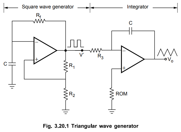
Basically,
triangular wave is generated by alternatively charging and discharging a
capacitor with a constant current. This is achieved by connecting integrator
circuit at the output of square wave generator. Assume that V' is high at +
Vsat. This forces a constant current (+ Vsat /R3) through
C (left to right) to drive Vo negative, linearly. When V' is low at -Vsat,
it forces a constant current (-Vsat/R3) through C (right
to left) to drive Vo positive, linearly. The frequency of the
triangular wave is same as that of square wave. This is illustrated in Fig.
3.20.2. Although the amplitude of the square wave is constant (± Vsat),
the amplitude of the triangular wave decreases with an increase in its
frequency, and vice versa. This is because the reactance of capacitor decreases
at high frequencies and increases at low frequencies.

In
practical circuits, resistance R 4 is connected across C to avoid the
saturation problem at low frequencies as in the case of practical integrator as
shown in the Fig. 3.20.3
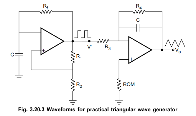
To obtain stable triangular wave at the
output, it is necessary to have 5R3 C2 > T/2, where T is the period of the
square wave input.
Another
triangular wave generator, which requires fewer components, is shown in the
Fig. 3.20.4.
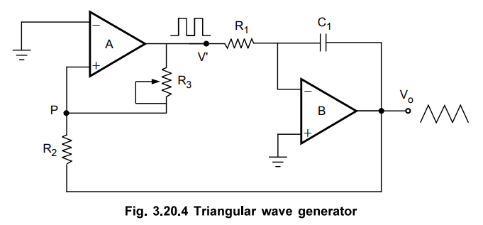
It
consists of a comparator (A) and an integrator (B). The output of comparator A
is a square wave of amplitude ± Vsat and is applied to the inverting (-) input
terminal of the integrator B. The output of integrator is a triangular wave and
it is fedback as input to the comparator A through a voltage divider R2
R3.
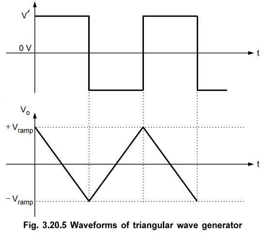
To
understand circuit operation, assume that the output of comparator A is at + Vsat-
This forces a constant current (+Vsat / R1) through C to
give a negative going ramp at the output of the integrator, as shown in the
Fig. 3.20.5. Therefore, one end of voltage divider is at a voltage +Vsat
and the other at the negative going ramp. When the negative going ramp reaches
a certain value - Vramp, the effective voltage at point p becomes slightly
below 0 V. As a result, the output of comparator A switches from positive
saturation to negative saturation (-Vsat). This forces a reverse constant
current (right to left) through C to give a positive going ramp at the output
of the integrator, as shown in the Fig. 3.20.5. When positive going ramp
reaches +Vramp, the effective voltage at point p becomes slightly
above 0 V. As a result, the output of comparator A switches from negative
saturation to positive saturation (+Vsat). The sequence then repeats
to give triangular wave at the output of integrator B.
1. Amplitude and Frequency Calculations
The
frequency and amplitude of the triangular wave can be determined as follows :
When comparator output is at +Vsat, the effective voltage at point P is given
by
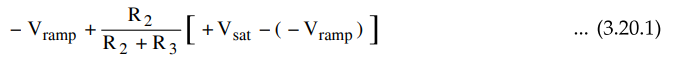
When
effective voltage at P becomes equal to zero, we can write above equation as,
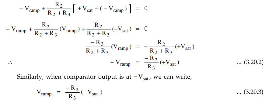
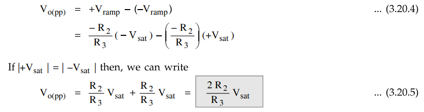
The
peak to peak amplitude of the triangular wave can be given as
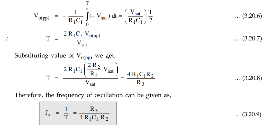
The
time taken by the output to swing from – Vramp, to + Vramp
(or from + Vramp to
-
Vramp) is equal to half the time period T/2. Refer Fig. 3.20.5. This
time can be calculated from the integrator output equation as follows:
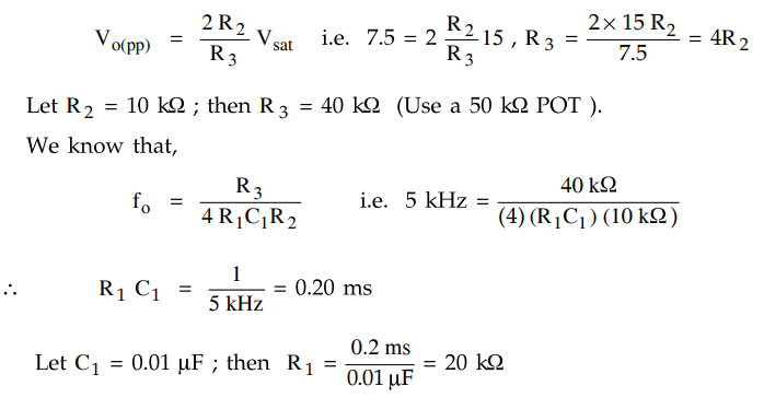
Example
3.20.1 Design a triangular wave generator as shown in
Fig. 3.20.4 such that fo = 5 kHz and Vo(pp) - 7.5 V. The op-amp
saturation voltage is ± 25 V.
Solution
:
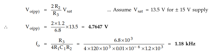
Example
3.20.2 In a triangular wave generator given R2 = 1.2
kQ, R3 = 6.8 kQ, R1 = 120 ko, C1 = 0.01 μF. Determine the peak to peak output
amplitude of triangular C1 wave and frequency of the triangular wave.
Dec.-14,
Marks 8
Solution: The peak output amplitude is,
Review Question
1. Draw and explain the operation of a triangular wave generator
and obtain an expression for its frequency.
Linear Integrated Circuits: Unit III: Applications of Op-amp : Tag: : Working Principle, Pulse, Circuit Diagram, Amplitude and Frequency Calculations, Solved Example Problems | Operational amplifier - Triangular Wave Generator using Op-amp
Related Topics
Related Subjects

Linear Integrated Circuits
EE3402 Lic Operational Amplifiers 4th Semester EEE Dept | 2021 Regulation | 4th Semester EEE Dept 2021 Regulation