Electric Circuit Analysis: Unit V: Resonance and coupled circuits
Tuned circuits
Tuned circuits are two types - (a) Single tuned, (b) double tuned. In radio frequency range (500 to 1600 kc/s), the application of signals is by these coupled circuits.
TUNED CIRCUITS
Tuned
circuits are two types - (a) Single tuned, (b) double tuned. In radio frequency
range (500 to 1600 kc/s), the application of signals is by these coupled
circuits. The coupled tuned circuits are used in radio receivers to produce
uniform response to modulated signals over a specified band width. They are
very useful in communication systems.
(a) Single Tuned Coupled Circuits
Consider
the circuit shown in the fig.5.40. A parallel resonant circuit on the secondary
is inductively coupled to coil 1. This coil 1 is excited by a source Eg.
Let Rg be the source resistance.
Let
R1, R2 be the resistances of coils 1 and 2 respectively
and let L1, L2 be the self-inductances of the coils 1 and
2 respectively.
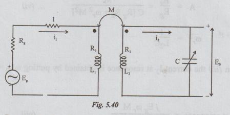
Assume
that Rg >> R1 >> jωL1 i.e., Ignore
R1 and jωL1, in comparison with Rg
Then,
the mesh equations are
When
the secondary side is tuned i.e., when the values of the frequency o, is such
that
From
equation (iii) the current I2 at resonance is obtained by putting ωL2
= 1/ωC and replacing ω by ωr.
Therefore
I2 at resonance = jEg ωrM / Rg R2
+ ωr2 M2 … (vii)
From
equations (vi) and (vii) it is observed that at resonance frequency E0,
I2 and A depend on M.
The
maximum value of E0 or A depends upon M. To get the condition for
maximum E0, dE0 / dM = 0
From
this, on simplification, we get
M
= √Rg R2 / ωr ... (viii)
i.e.,
When M = √Rg R2 / ωr , the output voltage is
maximum.
Therefore,
maximum output voltage
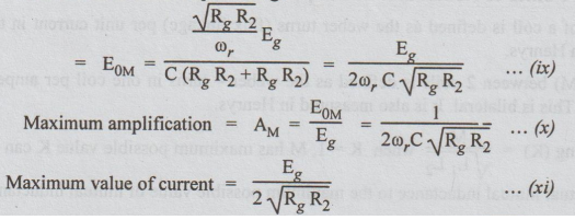
These
maximum values are obtained by substituting M = √Rg R2 / ωr
in expressions E0, A, and I2 at resonance.
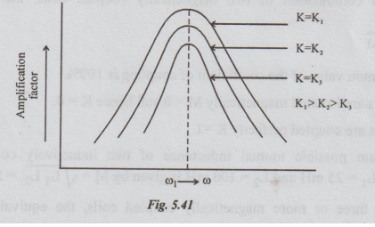
We
know that M = K√L1L2. By changing the coupling factor K,
we can vary M. The variation of amplification factor or output voltage with the
coefficient of the coupling is shown in the fig.5.41
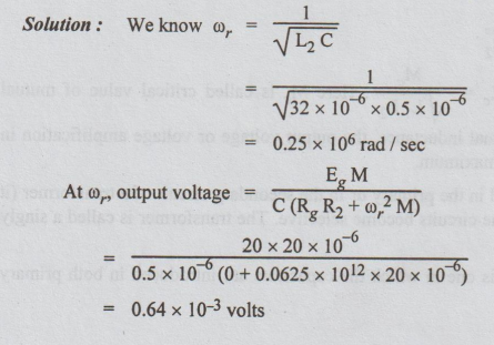
Example
9 In the single tuned resonant circuit, the applied voltage in a primary coil
Eg volts (assume Rg = 0), R1 = R2 = 5
Ω
L1 =L2 = 32μH, M = 20 μH
C
= (secondary side capacitance) = 0.5 μF
Determine
the resonant frequency and the output voltage at this frequency.
Solution:
Electric Circuit Analysis: Unit V: Resonance and coupled circuits : Tag: : - Tuned circuits
Related Topics
Related Subjects

Electric Circuit Analysis
EE3251 2nd Semester 2021 Regulation | 2nd Semester EEE Dept 2021 Regulation