Electric Circuit Analysis: Chapter - 1: Basic Circuit Analysis - DC
Two Mark Short Questions with Answer
Basic Circuit Analysis - DC | Electric Circuit Analysis
Electric Circuit Analysis : Chapter - 1 : Basic Circuit Analysis - DC : One Mark Questions and Answer
ONE MARK QUESTIONS AND ANSWER
1.
Define Electric current.
Electric
current is defined as rate of flow of electric charge.
i
= dq / dt amperes
where
q is the charge in coulombs. The unit of current is the ampere which is the
current that flows when 1 coulomb of charge is transferred in one second.
2.
Define Electrical potential or Voltage.
This
is generally measured between two points and its unit is volt. If the work done
in moving a charge of one coulomb between any two points is 1 joule, then we
say that the potential of one point with reference to the second point is 1
volt.
V
= dW / dQ
where
W is the work done in joules, Q is the charge in coulombs.
3.
What is meant by resistance?
The
resistance of a circuit is the property by which it opposes the flow of
current. This parameter measured in Ohms is responsible for energy dissipation.
4.
Define conductance.
The
reciprocal of resistance is called conductance. Its unit is Siemen and its
symbol is G.
G
= 1/R
5.
State Ohm's law (AU) Coimbatore/Mech - May 2003)
When
the temperature remains constant, current flowing through a circuit is directly
proportional to potential difference across the conductor.
Mathematically,
we may write
V∞
I (Temperature being constant) (or) V = IR,
where
'R' the constant of proportionality, becomes the resistance where V is in volts
and I is in amperes.
6.
Define electrical power.
The
rate at which work is, done in an electrical circuit is called electrical is
power and its unit is joule per second or watt. When one coulomb of electric
charge is be moved through a potential difference of one volt in one second,
the rate of work is 938 one joule per second or one watt. Hence, power in
electric circuits is obtained as a product of the voltage (E) and the current
(I).
P
= VI Watts
We
may write this
P
= I2 R (or)
P
= V2 IR
7.
What is meant by electrical energy? (AUCSE - May 2008)
Electrical
energy is the total amount of work done and hence is the product of od dr power
and time.
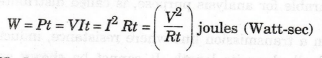
W
= Pt = VIt = I2 Rt = (V2 / Rt ) joules (Watt-sec)
8.
State Kirchhoff's laws.
Kirchhoff's
Current Law (I Law)
The
sum of the currents flowing towards a junction is equal to the sum of the
currents flowing away from it.
Kirchhoff's
Voltage Law (II Law)
In
a closed circuit, the sum of the potential drops is equal to the sum of the
potential rises.
9.
Write the general form of mesh analysis.
[R] [I] = [V]
10.
Define Lumped circuits.
A
network in which all the network elements are physically separable is known as
lumped network. Most of the electrical networks are lumped networks.
11.
Define linear and bilateral network. (AUBCE - May 2007).
Linear
Network
A
circuit or network whose parameters i.e., elements like resistors, inductors
and capacitors are always constant irrespective of the change in time, voltage,
temperature etc., is known as linear network. In linear network, the Ohm's law
can be applied and super position theorem can be used for solving mathematical
equations.
Bilateral
Network
A
circuit whose characteristics, behaviour is same irrespective of the direction
of current through various elements of it, is called bilateral network. Network
consisting only resistors is a good example for bilateral network.
12.
Define distributed elements. Given an example. (AU/BEE
- Dec 2006)
A
network in which the circuit elements like resistor, inductor, etc., cannot be
physically separable for analysis purpose, is called distributed network.
For
example, in a transmission line where resistance, inductance and capacitance
are distributed all along its length. It cannot be shown as a separate element,
anywhere in the circuit.
13.
Define Non-linear network.
A
circuit whose parameters change their values with change in time, temperature,
voltage etc., is known as non linear network. Ohm's law and law of
superposition do not applicable for this network.
14.
Define Unilateral network.
A
circuit whose operation, behaviour is dependent on the direction of the current
through various elements is called unilateral network. Example for unilateral
network is half wave diode rectifier.
15.
Define active and passive network.
Active
Network
A
circuit which contains a source of energy is called active network. Voltage and
current sources are energy sources.
Passive
Network
A
circuit which contains no energy source is called passive circuit. The passive
network contains resistor, capacitor and inductor.
16.
What are the types of circuit elements?
1.
Active element:
Voltage
and current sources
2.
Passive element:
Resistor,
inductor, capacitor
17.
What are the dependent source? Name the different types? (AU/Coimbatore/EEE
- May 2003)(AU/DIE, May 2001
Dependent
sources
A
dependent voltage or current source is one which depends on some other quantity
in the circuit which may be either a voltage or a current. Such a source is
represented by a diamond shaped symbol.
There
are four types of dependent sources
1.
Voltage dependent voltage source
2.
Current dependent voltage source
3.
Voltage dependent current source
4.
Current dependent current source
18.
Differentiate between time invariant and time variant sources.
(AU/Coimbato re/EBBI May 2008);
Time
invariant source
Source
which can deliver or absorb energy continuously is called time invariant source.
Eg:
Battery, DC generator, AC generator
Time
variant source
Time
variant source is one which depends on some other quantity in the circuit which
may be either a voltage or a current.
Eg:
Transistors, operational amplifier.
19.
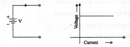
What is an ideal voltage source and an ideal current source?
Ideal
Voltage Source
Ideal
voltage source is a source which delivers energy with specified terminal
voltage, which is independent of the current supplied by the source. Such a
voltage which source maintains constant specified voltage for all currents
supplied by the source is called an ideal voltage source. For ideal voltage
source, the internal impedance is zero.
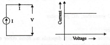
Ideal
Current Source
The
ideal current source is a source which delivers energy with a specified current
which is independent of the voltage at its terminals. Such a current source
which maintains a constant specified current for all voltages is called an
ideal current source.
20.
Draw the V-I relationship of an ideal voltage source.
21.
What are the ideal sources of electrical energy?
1.
Ideal voltage sources
2.
Ideal current source
22.
Draw the V-I relationship of an ideal current source.
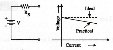
23.
Draw the V-I relationship of a practical voltage source.
24.
Draw the V-I relationship of practical current source.
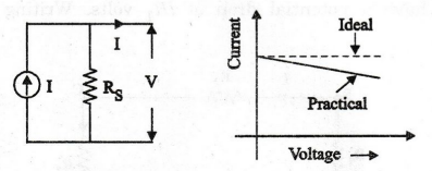
25.
State Kirchhoff's current law.
Kirchhoff's
Current Law (I Law)
Statement
The
sum of the currents flowing towards a junction is equal to the sum of the
currents flowing away from it.
In
figure, A is a junction (or node) formed by six conductors. The currents in
these conductors are 11, 12, ... I6. Some of these currents are flowing towards
A and others flowing away from it.
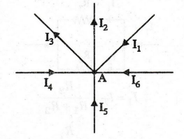
According
to Kirchhoff's Law,
I1
+ I4 + I5 + I6
= I2 + I3
Current
flowing towards A = Current flowing away from A
26.
State Kirchhoff's voltage law
Kirchhoff's
Voltage Law (II Law)
Statement
In
a closed circuit, the sum of the potential drops is equal to the sum of the
potential rises.
In
figure, ABCDA form a closed circuit. Assuming the current direction as shown,
from A to B, we have a potential drop of IR1 volts. Writing for the entire loop
ABCDA, we have,
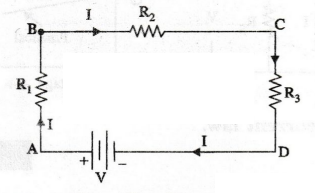
Sum
of potential drops = IR1+ IR2 + IR3
Potential
rise from D to A = V
IR1
+ IR2 + IR3 = V
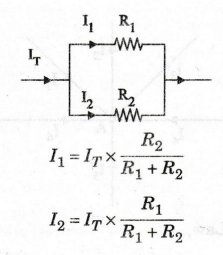
27.
Write the current division rule.
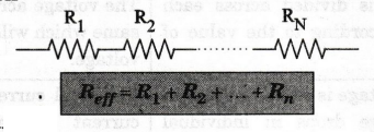
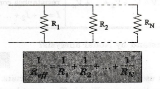
28.
What is the equivalent resistance when 'N' resistors are in (a) series (b) in
parallel? (AUECE - May
2007),
(a)
Series Connection
(b)
Parallel Connection
29.
Mention the limitations of Ohm's law. (AUCoimbatore . Mech)
1.
Ohm's law does not apply to all non-metallic conductors.
2.
It does not also apply to non-linear devices such as zener diode, vacuum tubes
etc.
3.
Ohm's law is true for metal conductors at constant temperature. If the
temperature changes, the law is not applicable.
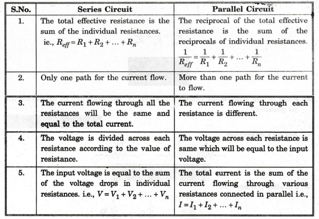
30.
Compare series and parallel circuit.
31.
What do you understand by Nodal analysis?
The
nodal method is used to analyze multisource circuits. In this method that we
solve the simultaneous equations using Kirchhoff's current law (KCL) applied at
various nodes in an electric circuit. Node is defined as junction or joining
point two or more component terminals.
32.
Write the equivalent resistance when two resistors are connected in parallel.
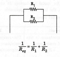
Req
= R1 R2 / R1 + R2
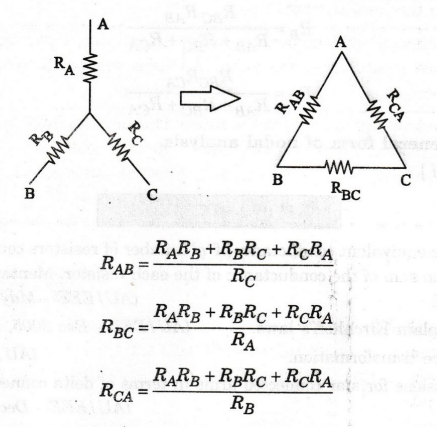
33.
Give the expression for star to delta transformation.
34.
All the resistors in delta are equal and converted into star network. Which
network has the larger resistance?
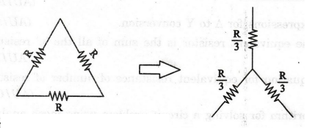
Delta
network has larger resistance
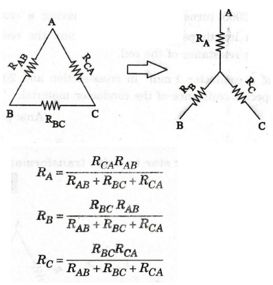
35.
Give the expression for delta to star conversion.
36.
Write the general form of nodal analysis.
[G][V]=[I]
Electric Circuit Analysis: Chapter - 1: Basic Circuit Analysis - DC : Tag: : Basic Circuit Analysis - DC | Electric Circuit Analysis - Two Mark Short Questions with Answer