Electrical Machines II: UNIT I: b. Armature Reaction and Regulation of Alternators
Two Marks Questions with Answers
Armature Reaction and Regulation of Alternators | Electrical Machines
Engineering Electrical Machines - II : UNIT I : Armature Reaction and Regulation of Alternators : Anna University Two Marks Questions & Answers
Two Marks Questions with Answers
Q.
1 Define voltage regulation of alternator.
Ans. :
The
voltage regulation of an alternator is defined as the change in its terminal
voltage when full load is removed, keeping field excitation and speed constant,
divided by the rated terminal voltage.
So
if Vph = Rated terminal
voltage and Eph = No load induced e.m.f.
then
voltage regulation is defined as,
%
Regulation = Eph - Vph / × 100
Q.
2 What are the factors that contribute reduction in terminal voltage of a
loaded alternator ?
Ans. :
1.
Armature reaction
2.
Load current and
3.
Load power factor.
Q.
3 Define voltage regulation. Name two methods used to determine voltage
regulation of alternators.
Ans. :
The
voltage regulation of an alternator is defined as the change in its terminal
voltage when full load is removed, keeping field excitation and speed constant,
divided by the rated terminal voltage.
The
two methods are :
1.
Synchronous impedance method or E.M.F. method and
2.
Ampere-turns method or M.M.F. method
Q.
4 List the three important parameters of an armature winding of an alternator.
Ans. :
1.
Armature resistance Ra,
2.
Armature leakage reactance XL and
3.
Reactance corresponding to armature reaction denoted as Xar.
Q.
5 Define leakage flux. State its effect.
Ans. : When
armature carries a current, it produces its own flux. Some part of this flux
completes its path through the air around the conductors itself. Such a flux is
called leakage flux. This leakage flux makes the armature winding
inductive in nature. So winding possesses a leakage reactance, in addition to
the resistance due to which there is additional voltage drop across the
armature winding when an alternator is loaded.
Q.
6 Define armature reaction in an alternator.
Ans. : When the load is connected to the
alternator, the armature winding of the alternator carries a current. So there
are two fluxes present in the air gap, one due to armature current while second
is produced by the field winding called main flux. The flux produced by the
armature is called armature flux. So effect of the armature flux on the main
flux affecting its value and the distribution is called armature reaction.
Q.
7 State the nature of armature reaction for the various types of load power
factors.
Ans. : 1. Distorting effect of armature
reaction under unity p.f. condition of the load is called cross magnetising
effect of armature reaction.
2.
Armature flux tries to cancel the main flux when the load power factor is
lagging. Such an effect of armature reaction is called demagnetising effect of
the armature reaction.
3.
An effect of armature reaction due to leading power factor of the load is to
assist the field flux which is called magnetising effect of the armature
reaction.
Q.
8 What is armature reaction reactance and synchronous reactance of an
alternator.
Ans. : To quantify the voltage drop due to the
armature reaction, armature winding is assumed to have a fictitious reactance.
This fictitious reactance of the armature is called armature reaction reactance
denoted as Xar Ω/ph. And the drop due to armature reaction can be
accounted as the voltage drop across this reactance as Ia Xar.
The
sum of the fictitious armature reaction reactance accounted for considering
armature reaction effect and the leakage reactance of the armature is called
synchronous reactance of the alternator denoted as Xs.
So
Xs = XL + XAR Ω/ph
Q.
9 Define synchronous impedance of an alternator.
Ans. : An impedance obtained by combining
per phase values of synchronous reactance and armature resistance is called
synchronous impedance of the alternator denoted as Zs.
So 
Q.
10 Draw the equivalent circuit of an alternator.
(Refer
section 2.7)
Q.
11 State the voltage equation of an alternator.
Ans. : The voltage equation of an alternator
is,

Q.
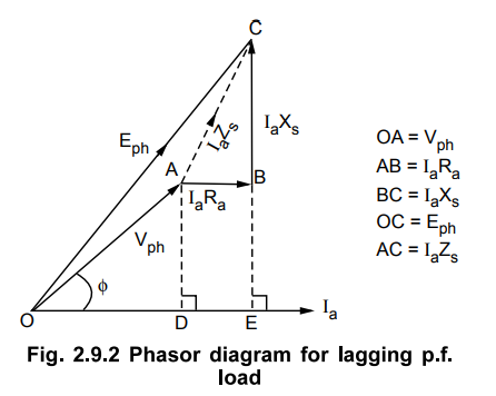
12 Draw the vector diagram of loaded alternator with lagging power factor.

Q.
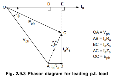
13 Draw the vector diagram of loaded alternator with leading power factor.
Q.
14 Draw the vector diagram of loaded alternator with unity power factor.
Q.15
State the expression for induced e.m.f. in terms of winding parameters for any
power factor condition.
Ans. : In general for any power factor
condition induced e.m.f. per phase is given by,
(Eph)2
= (Vph cos ϕ + IaRa)2 + (Vph sin
ϕ ± IaXs)2
+
Sign for lagging p.f. loads and - Sign for leading p.f. loads
Vph
= Per phase rated terminal voltage and Ia = Per phase armature
current
Q.
16 Draw and comment on load
characteristics of an alternator.
(Refer
section 2.10)
Q.
17 Draw the circuit diagram for open
circuit and short circuit test on alternator.
(Refer
section 2.13)
Q.
18 What data is required to calculate regulation by synchronous impedance
method 7
Ans. :
1.
The armature resistance per phase (Ra).
2.
Open circuit characteristics which is the graph of open circuit voltage against
the field current. This is possible by conducting open circuit test on the
alternator.
3.
Short circuit characteristics which is the graph of short circuit current
against field current. This is possible by conducting short circuit test on the
alternator.
Q.
19 How to obtain synchronous impedance from E.M.F. method ?
Ans. :
From
E.M.F. method, synchronous impedance is given by,

Q.
20 State the procedure to conduct open and short circuit tests on an
alternator.
(Refer
sections 2.13.1 and 2.13.2)
Q.
21 State the advantages and limitations of synchronous impedance method.
Ans. :
The
advantages are : 1. The value of synchronous impedance Zs for any load
condition can be calculated. 2. Regulation of the alternator at any load condition
and load power factor can be determined. 3. Actual load need not be connected
to the alternator. 4. The method can be used for very high capacity
alternators.
The
main limitation of this method is that the method gives large values of
synchronous reactance. This leads to high values of percentage regulation than
the actual results. Hence this method is called pessimistic method.
Q.
22 For which two purposes m.m.f. is required for an alternator ?
Ans. :
1.
It must have an m.m.f. necessary to induce the rated terminal voltage on open
circuit.
2.
It must have an m.m.f. equal and opposite to that of armature reaction m.m.f.
Q.
23 What is the use of Potier triangle ?
Ans. :
In
alternators, armature leakage reactance is the voltage drop while the armature
reaction is m.m.f. quantity. The Potier triangle is used to separate the
armature leakage reactance and the armature reaction m.m.f. from each other.
Hence the regulation obtained by the Potier method is more accurate than the
other methods.
Q.
24 Define short circuit ratio for an alternator.
Ans. :
The
short circuit ratio is the ratio of the excitation required to produce open
circuit voltage equal to the rated voltage to the excitation required to
produce rated full load current under short circuit.
Mathematically,
SCR (Short Circuit Ratio) = If for rated open circuit voltage / If
for rated short circuit current
Q.
25 Explain why an alternator with low value of short circuit ratio has lower
limit of stability.
Ans. :
The
synchronous power is inversely proportional to Xs. This is the power which
keeps alternators in synchronism during parallel operation and maintains the
stability. Any disturbances from equilibrium conditions are compensated by
synchronizing power. For low value of SCR, Xs is very large and synchronizing
power is very low. As synchronizing power decreases, tendency of alternators to
remain in synchronism decreases. This decreases the stability. Thus low SCR
puts the stability limit.
Q.
26 State the assumption made in the Potier method and explain the effect of
these assumptions on the accuracy of the voltage regulation.
Ans. :
1.
In the entire calculation procedure of Potier method, the armature resistance
is assumed to be negligibly small.
2.
In a zero power factor test, inductors are assumed to be a perfect zero power
factor condition.
3.
The leakage reactance of the machine remains unchanged at all the conditions
including zero power factor and short circuit conditions.
Q.
27 Why is the synchronous impedance method used to determine voltage regulation
of synchronous machine called pessimistic ?
Ans. :
The
synchronous impedance is practically variable and not constant. If there is
saturation, it remains constant but it decreases towards the saturation while
it increases for the low saturation region. In synchronous impedance method, in
short circuit test, the field current required is very small to pass the short
circuit current hence the flux density is low and the region is low saturation
region. Hence the synchronous impedance is much higher than its normal value.
Thus the drop IaZsis high due to which the regulation is also high than the
actual value, by synchronous impedance method. Hence the method is called
pessimistic.
Q.
28 Write down the causes for reduction in terminal voltage of alternator from
it's no load value Eo to V for a lagging power factor.
Ans. :
On
no load armature current is zero so there are no voltage drops existing. But on
lagging power factor load, the armature current flows which causes the voltage
drop across the armature resistance and armature leakage reactance. Similarly
there is demagnetising armature reaction existing for lagging power factor load
which deceases the main flux and causes the reduction in the terminal voltage.
Q.
29 What are the reasons for drop in voltage from no load to full load?
Ans. :
As
armature current increases as load changes from no load to full load, the
following voltage drops take place,
1.
The voltage drop across the armature resistance, IaRa.
2.
The voltage drop across the armature leakage reactance.
3.
The drop in voltage due to the armature reaction effect.
Q.
30 Under what condition the terminal voltage of an alternator will be greater
than induced e.m.f. ?
Ans. :
On
leading power factor loads, the armature reaction is magnetising. Due to this,
the main flux increases which is responsible for the increase in the terminal
voltage. Hence under loading power factor loads the terminal voltage is greater
than the induced e.m.f.
Q.
31 What are the experimental data required for Potier method ?
Ans. :
1.
It requires open circuit characteristics by conducting open circuit test.
2.
The graph of terminal voltage against excitation (field current) when
delivering full load zero power factor current. This is achieved by conducting
zero power factor test.
Q.
32 What is the necessity for predetermination of voltage regulation ?
Ans. :
Most
of the alternators are manufactured with large power rating, hundreds of kW or
MW, and also with large voltage ratings upto 33 kV. For Alternators of such
power and voltage ratings, conducting direct load test is not possible. Hence
other indirect methods of testing are used and the performance like voltage
regulation then can be predetermined at any desired load currents and power
factors.
Q.
33 Name the various methods for predetermining the voltage regulation of
alternators.
Ans. :
1.
Synchronous impedance or EMF method.
2.
Ampere-turn or MMF method.
3.
Potter's triangle or zero power factor method.
4.
A.S.A. modification of MMF method.
Electrical Machines II: UNIT I: b. Armature Reaction and Regulation of Alternators : Tag: Engineering Electrical Machines - II : Armature Reaction and Regulation of Alternators | Electrical Machines - Two Marks Questions with Answers
Related Topics
Related Subjects

Electrical Machines II
EE3405 Machine 2 EM 2 4th Semester EEE Dept | 2021 Regulation | 4th Semester EEE Dept 2021 Regulation