Transmission and Distribution: Unit II: (a) Modelling and Performance of Transmission Lines
Two Marks Questions with Answers
Modelling and Performance of Transmission Lines
Transmission and Distribution: Unit II: (a) Modelling and Performance of Transmission Lines : Two Marks Questions with Answers
Two Marks Questions with
Answers
Q.1 Define voltage regulation of
transmission lines.
Ans. : Voltage
regulation of a transmission line is defined as the difference in voltage at
the receiving end of the transmission line at the no load and full load
expressed as a percentage of the voltage at the receiving end with supply
frequency and voltage at sending end remaining unchanged. Mathematically it is
given as,
%
Voltage Regulation = VNoLoad - VFullLoad / VFullLoad × 100
Q.2 How transmission lines are
classified ?
Ans. : Based on the
line length and voltage, the overhead transmission lines are classified as
i) Short transmission line
ii) Medium transmission line
iii) Long transmission line
Q.3 What do you mean by short transmission
line ?
Ans. : If the
transmission line length is about 50 km and the line voltage is low i.e. about
20 kV or less then that line is treated as short transmission line.
Q.4 What do you mean by medium
transmission line ?
Ans. : If the
transmission line length is lying between 50 km and 150 km with moderately high
line voltage in between 20 kV and 100 kV then that line is treated as medium
transmission line.
Q.5 What do you mean by long
transmission line ?
Ans. : If the
transmission line length is more than 150 km with very high line voltage above
100 kV then that line is considered as long transmission line.
Q.6 What is Ferranti effect ?
Ans. : In case of long
transmission line under no load conditions, the voltage at the receiving end is
found to be more than that at the sending end because of the effect of line
capacitance. This is called Ferranti effect.
Q.7 Write the expression for
characteristic impedance and the propagation constant.
Ans. : The expression
for characteristic impedance and the propagation constant is given as,
Characteristic impedance, Zc = √Z / Y ; Z
is series impedance and Y is shunt admittance of line
Propogation constant, ɤ = √ZY ; Z is
series impedance and Y is shunt admittance of line
Q.8 What is surge impedance ?
Ans. : The surge
impedance is defined as the ratio of the amplitudes of voltage and current of a
single wave propagating along the line; that is, a wave travelling in one
direction in the absence of reflections in the other direction. Its SI unit is
Ohm. It is purely real with no reactive component.
Q.9 What are units for generalized
circuit constants A, B, C and D ?
Ans. : A and D are
dimensionless constants. B has unit of impedance i.e. Ohm (Ω) while unit of C
is mho which is that of admittance.
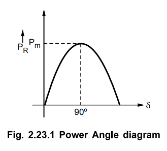
Q.10 Draw the power angle diagram of a
transmission line.
Ans. : The power angle
diagram of a transmission line is as shown in the Fig. 2.23.1.
Q.11 Mention the approximate value of
surge impedance for overhead line.
Ans. : The approximate
value of surge impedance for overhead lines is 400 Ω while typically it is in
the range of 400 Ω to 600 Ω.
Q.12 In long transmission lines and
cables receiving end voltage is greater than sending end voltage during light
load or no load operation. Why ?
Ans. : In a long
transmission lines and cables it is observed that the receiving end voltage is
greater than sending end voltage during light load or no load operation due to
Ferranti effect. Under this light load condition, the line capacitance generate
more reactive power than the reactive power which is absorbed which results in
greater voltage at receiving end than that at sending end.
Q.13 Define transmission efficiency.
Ans. : The transmission
efficiency is defined as the ratio of power at the receiving end to the power
at the sending end expressed as a percentage. Mathematically it is given as,
% Transmission efficiency = Power at
receiving end (PR ) / Power at sending end (PS ) × 100
Q.14 For controlling reactive power,
what adjustment should be done in transformer present in the system ?
Ans. : The
transformers are equipped with taps on the windings to adjust the reactive
power flow through the transformer.
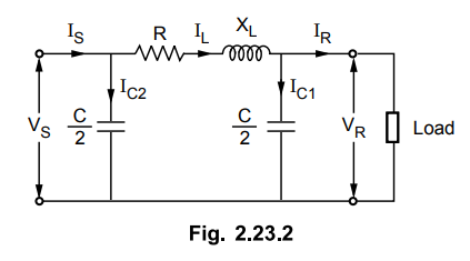
Q.15 Draw the nominal K representation
of a transmission line.
Ans. : The nominal K
representation of a transmission line is shown in the Fig. 2.23.2.
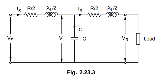
Q.16 Draw the nominal T representation
of a transmission line.
Ans. : The nominal T
representation of a transmission line is shown in the Fig. 2.23.3.
Q.17 What is power circle diagram ?
Ans. : The real and
reactive powers at sending and receiving end can be computed mathematically and
the transmission line characteristics can be represented graphically. By taking
sending end or receiving end voltage or current as a reference, these
characteristics can be plotted which represent circle and the corresponding
diagram is called circle diagram. The real power is plotted on X axis while the
reactive power is on Y axis.
Q.18 What is surge impedance loading ?
Ans. : The Surge
Impedance Loading (SIL) of a line is defined as the power delivered by a line
to a purely resistive load equal to its surge impedance. The line is assumed to
have no resistance. The reactive power is neither produced nor absorbed.
Mathematically it is given as,
SIL = V2R / Zc
Q.19 List out any two reasons for line
loss in a transmission line.
Ans. : The losses in
line are resistive loss which is due to finite small resistance associated with
the line as perfect conductor never exists in practice. The other loss is
corona loss which is due to corona effects which is caused due to ionization of
air molecules near the transmission line conductors and carries current in the
air along the wire causing the loss.
Q.20 State the condition for maximum
power delivered.
Ans. : The maximum
power is delivered when power angle δ is 90°.
Q.21 Mention the significance of surge
impedance loading.
Ans. : The Surge
Impedance Loading (SIL) of a line is defined as the power delivered by a line
to a purely resistive load equal to its surge or characteristics impedance. SIL
is called natural power of the line. It helps in expressing power transmitted
by a line in terms of per unit of SIL which is the ratio of the power
transmitted to the surge impedance loading. The permissible loading of a
transmission line can be expressed as a fraction of its SIL and it provides a
comparison of load carrying capabilities of lines.
Q.22 What is shunt compensation ?
Ans. : Compensation of
a line with the help of a shunt capacitor across the line in order to improve
the power factor and voltage profile as well as to reduce the losses is known
as shunt compensation.
Q.23 What are the factors which govern
the performance of a transmission line ?
Ans. : The
transmission line performance is mainly governed by its four parameters -
series resistance and inductance, shunt capacitance and conductance where the
shunt conductance is often neglected as it is very small. All these parameters
are distributed over the length of the line. Based on these parameters the
performance measures of transmission lines are the transmission efficiency and
voltage regulation both expressed as percentage.
Q.24 What is the range of surge
impedance in case of underground cables ?
Ans. : The approximate
value of surge impedance for underground cables is 40 Ω while typically it is
in the range of 40 Ω to 60 Ω.
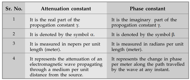
Q.25 Distinguish between attenuation and
phase constant.
Ans. :
Q.26 What is the use of power circle
diagram ?
Ans. : The power
circle diagrams are useful in studying various aspects power transmission at
sending and receiving end. It aids in determining real or active power P,
reactive power Q power angle δ, power factor at given load conditions, also
voltage conditions and impedance Z of the line.
Q. 27 What
are the types of compensation used in case of transmission lines ?
Ans. : The
types of compensation used in case of transmission lines are series
compensation and shunt compensation.
Q.28 What are the advantages of series
compensation ?
Ans. : The advantages
of series compensation are
i) Increase in power transmission
capacity of line
ii) Improvement in system stability
iii) Improved voltage regulation
iv) Load division between parallel
circuits
v) Damping of power swings and
transients
Q.29 What are the disadvantages of
series compensation ?
Ans. : The
disadvantages of series compensation are
i) Increase in fault current level due
to reduced reactance affecting short circuit current rating of the circuit
breaker
ii) Change in natural frequency of the
transmission system. Gives rise to high torsional losses
iii) Possibility of faulty operation of
distance relays
iv) Possibility of hunting increases
v) High voltage may occur across
capacitor terminals due to phenomenon called ferroresonance which may damage
capacitors
Q.30 What are the main constraints in
capability of power transfer for transmission line ?
Ans. : The main
constraints in capability of power transfer for transmission line are thermal
limits, voltage drop limit and transient and steady state stability limits.
Q.31 What are the advantages of shunt
compensation ?
Ans. : The advantages
of shunt compensation are
i) Increase in kW rating of generators,
transformers and lines
ii) Reduction in line current
iii) Reduction in losses taking place in
power transformers and cables
iv) Avoids overloading of transformers
and switchgears
v) Improved voltage is obtained at
receiving end
vi) Distinguish between series and shunt
capacitors used for compensation.
Q.32 What are the effects of shunt
compensation ?
Ans. : The effects of
shunt compensation are
i) Reduction in line losses due to
generation of reactive power.
ii) Reduction in line current.
iii) It improves the power factor of the
transmitted power.
iv) It reduces the voltage drop and it
is uniformly distributed along the length of the line.
Q.33 Why series compensation is used ?
Ans. : The
series compensation is used to
i) increase power transmission capacity
of line.
ii) improve system stability.
iii) improve voltage regulation.
iv) damp out power swings and
transients.
Q.34 What do you mean by voltage
stability ?
Ans. : The voltage
stability corresponds to limit on maximum power transfer through the
transmission line beyond which the voltage collapses and stability is lost.
Q.35 Distinguish between voltage
stability and rotor angle stability.
Ans. :

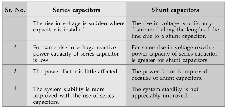
Q.36 Distinguish between series and
shunt capacitors used for compensation.
Ans. :
Transmission and Distribution: Unit II: (a) Modelling and Performance of Transmission Lines : Tag: : Modelling and Performance of Transmission Lines - Two Marks Questions with Answers
Related Topics
Related Subjects

Transmission and Distribution
EE3401 TD 4th Semester EEE Dept | 2021 Regulation | 4th Semester EEE Dept 2021 Regulation