Transmission and Distribution: Unit IV: Underground Cables
Type of Cable
Belted - Screened - Super Tension (S.T.) - Oil Filled - Gas Pressure
Question : 1. With neat diagrams explain constructional features of various types of cables.
Type of Cable
The type of a cable is basically decided
based on the voltage level for which it is manufactured and the material used
for the insulation such as paper, cotton, rubber etc. The classification of
cables according to the voltage levels is,
1. Low tension cables (L.T. cables) :
These are used for the voltage levels upto 6.6 kV. The electrostatic stresses
in L.T. cables are not severe hence no special construction is used for L.T.
cables. The paper is used as an insulation in these cables. Sometimes resin is
also used which increases the viscosity and helps to prevent drainage.
The Fig. 6.4.1 shows the cross-section
of a single core L.T. cable. It consists of a circular core of stranded copper
or aluminium. The conductor is insulated by impregnated paper. Over the paper
insulation, the lead sheath is provided. Then a layer of compounded fibrous
material is provided. Then armouring is provided and finally covered again with
a layer of fibrous compounded material.

Many a times, L.T. cables are not
provided with armouring, to avoid excessive sheath losses. The simple
construction and the availability of more copper section are the advantages of
L.T. single core cable.
2. Medium and High Tension Cables (H.T.
cables) : The three phase medium and H.T. cables are three
core cables. For voltages upto 66 kV, the three core cables i.e. multicore cables
are used. These cables are classified as,
a. H.T. cables upto 11 kV level which
are belted type.
b. Super Tension (S.T.) cables for 22 kV
and 33 kV levels which are screened cables.
c. Extra High Tension (E.H.T.) cables
for voltage levels from 33 kV to 66 kV which are pressure cables.
Let us see the constructional features
of these types of three core cables.
1. Belted Cables
As mentioned earlier, these are used
construction of belted cable is shown in the Fig. 6.4.2.

The cores are not circular in shape. The
cores are insulated from each other by use of impregnated paper. The three
cores are grouped together and belted with the help of a paper belt. The gaps
are filled with fibrous material like jute. This gives circular cross-sectional
shape to the cable. The belt is covered with lead sheath which protects cable
from moisture and also gives mechanical strength. The lead sheath is finally
covered by jute like fibrous compounded material.
The electric field in single core cable
is radial while it is tangential in case of three core cables. Hence the
insulation is subjected to tangential electrical stresses rather than radial
one. The paper has good radial strength but not tangential strength. Similarly
paper resistance along the radius is much larger than resistance along
tangential path. The same is true for dielectric strength also. The fibrous
material is also subjected to the tangential electrical stresses, for which,
the material is weak. Hence under high voltage cases, the cumulative effect of
tangential electrical stresses is to form spaces inside the cable due to
leakage currents. Such air spaces formed inside the insulation is called void
formation. This void formation is dangerous because under high voltage, spaces
are ionized which deteriorates the insulation which may lead to the breakdown
of the insulation. Hence the belted cables are not used for the high voltage
levels. Another disadvantage of the belted cable is large diameter of paper
belt. Due to this, wrinkles are formed and gaps may be developed if the cable
is bended. To overcome all these difficulties, the screened type cables are
used.
2. Screened Type Cables
These cables are used for the voltage
levels of 22 kV and 33 kV. The two types of screened cables are 1. H type
cables and 2. S.L. type cables.
a. H-Type Cables
The cable is designed by M. Hochstadter
and hence the name given to it is H-type cable. There is no paper belt in this
type of cable. Each conductor in this cable is insulated with a paper, covered
with a metallic screen which is generally an aluminium foil. The construction
is shown in the Fig. 6.4.3.

The metallic screen touches each other.
Instead of paper belt, the three cores are wrapped with a conducting belt which
is usually copper woven fabric tape. Then there is lead sheath. The conducting
belt is in electrical contact with the metallic screen and lead sheath. After
lead sheath there are layers of bedding, armouring and serving. The metallic
screen helps to completely impregnate the cable which avoids the possibility of
formation of voids and spaces. The conducting belt, the three metallic screens
and lead sheath are at earth potential, due to which electrical stresses are
radial in nature. This keeps the dielectric losses to minimum. Another
advantage of metallic screens is increase in the heat dissipation which reduces
the sheath losses. Due to these advantages, current carrying capacity of these
cables increases. In special cases, the use of these cables can be extended upto
the 66 kV level.
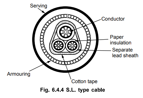
b. S.L. Cables
The name S.L. stands for separate lead
screened cables. In this cable, each core is insulated with an impregnated
paper and each one is then covered by separate lead sheath. Then there is a
cotton tape covering the three cores together using a proper filler material.
Then there are the layers of armouring and serving. The difference between
H-type and S.L. type cable is that in S.L. type a common lead sheath covering
all the three cores is absent while each core is provided with separate lead
sheath. This allows bending of the cables as per the requirement. The
construction of S.L. type cable is shown in the Fig. 6.4.4.
The three cores in this type of cable
are as good as three separate single core cables.
The various advantages of S.L. type
cable are,
1. Due to individual lead sheath, core
to core fault possibility gets minimised.
2. The electrical stresses are radial in
nature.
3. Due to absence of overall lead
sheath, bending of cable is easy.
4. The dielectric which gets subjected
to electric stresses is paper which is homogeneous hence there is no
possibility of formation of voids.
5. Metal sheath increases the heat
dissipation which increases the current carrying capacity.
A combination of H-type and S.L. type
cable called H.S.L. cable also can be used.
The limitations of screened cables which
are also called solid type cables are,
1. It uses solid insulation only like
paper. When the conductor temperature increases, the paper gets expanded. This
eventually stretches the lead sheath.
2. When the load on the cable decreases,
it cools down and there is contraction of lead sheath. Due to this air may be
drawn into the cable forming voids. This deteriorates the cable insulation.
3. Moisture may be drawn in alongwith
the air which deteriorates the dielectric strength of dielectric.
4. Mechanical shock can cause voids. The
breakdown strength of voids is much less than insulation. Hence voids can cause
permanent damage to the cables.
3. Super Tension (S.T.) Cables
In solid type cables separate
arrangement for avoiding void formation and increasing dielectric strength is
not provided. Hence those cables are used maximum upto 66 kV level. The S.T.
cables are intended for 132 kV to 275 kV voltage levels.
In such cables, the following methods
are specially used to eliminate the possibility of void formation :
1. Instead of solid type insulation, low
viscosity oils under pressure is used for impregnation. The channels are used
for oil circulation and oil is always kept under pressure. The pressure
eliminates completely, the formation of voids.
2. Using inert gas at high pressure in
between the lead sheath and dielectric.
Such cables using oil or gas under
pressure are called pressure cables and are of two types,
a. Oil filled cables b. Gas pressure
cables
4. Oil Filled Cables
In case of oil filled cables, the
channels or ducts are provided within or adjacent to the cores, through which
oil under pressure is circulated.

The Fig. 6.4.5 shows the construction of
single core oil filled cable. It consists of concentric stranded conductor but
built around a hollow cylindrical steel spiral core. This hollow core acts as a
channel for the oil. The oil channel is filled in a factory and the pressure is
maintained in the oil by connecting the oil channel to the tanks which are
placed at the suitable distances along the path of the cable.
The oil pressure compresses the paper
insulation, eliminating the possibility of formation of voids. When cable is
heated, the oil expands but expanded oil is collected in the tank. While when
cable is cooled, extra oil is supplied by the tank to maintain the oil
pressure. In this type of cable the oil channel is within the conductor, hence
it is called single core conductor channel oil filled cables. The other
construction of the cable is similar to that of solid type cables.
Another type of single core oil filled
cable is the sheath channel oil filled cable. In this type, the conductor is
solid with a paper insulation. While the oil ducts are provided between the
dielectric and the lead sheath.
The construction of sheath channel oil
filled cable is shown in the Fig. 6.4.6. The laying of such cables must be done
very carefully.

The three core oil filled cables use the
shielded type construction. The oil channels are located in the spaces which
are normally occupied by the filler material. The three oil channels are of
perforated metal ribbon tubing.
All the channels are at earth potential.
The construction is shown in the Fig. 6.4.7. As the pressure tanks are required
all along the route of these cables, the lengths of these cables are limited.
Leakage of oil is another serious problem associated with these cables.
Automatic signalling units are located to indicate the fall in oil pressure in
any of the phases.

a. Advantages
The various advantages of oil filled
cables are,
1. The thickness of insulation required
is less hence smaller in size and weight.
2. The thermal resistance is less hence
current carrying capacity is more.
3. The possibility of voids is
completely eliminated.
4. The allowable temperature range is
more than solid type cables.
5. Reduced possibility of earth fault.
This is because in case of any defect in lead sheath, oil leakage starts, which
can be noticed before earth fault occurs.
6. Perfect impregnation is possible.
b. Disadvantages
The disadvantages of oil filled cables
are,
1. The initial cost is very high.
2. The long lengths are not possible.
3. The oil leakage is serious problem
hence automatic signalling equipment is necessary.
4. The laying of cable is difficult and
must be done very carefully.
5. Maintenance of the cables is also
complicated.
5. Gas Pressure Cables
In case of gas pressure cables, an inert
gas like nitrogen at high pressure is introduced lead sheath and dielectric.
The pressure is about 12 to 15 atmospheres. Due to such a high pressure there
is a radial compression due to which the ionization is totally eliminated. The
working power factors of such cables is also high.

The Fig. 6.4.8 shows the section of a
gas pressure cable. The cable is triangular in shape and installed in the steel
pipe. The pipe is filled with the nitrogen at 12 to 15 atmospheric pressure.
The remaining construction is similar to that of solid type cable but the
thickness of lead sheath is 75 % of that of solid type cable. There is no
bedding and serving. The pressure cable was firstly designed by Hochstadter, Vogel
and Bowden.
The triangular shape lead sheath acts as
a pressure membrane. The shape reduces the weight and provides the low thermal
resistance. The high pressure creates the radial compression to close any
voids. The steel pipe is coated with a paint to avoid corrosion.
During heating, the cable compound
expands and a sheath which acts as a membrane becomes circular in such a case.
When cable cools down the gas pressure acting via sheath forces compound to
come back to the noncircular normal shape. Due to good thermal characteristics,
fire quenching property and high dielectric strength, the gas SF6 is also used
in such cables.
a. Advantages
The various advantages of gas pressure
cables are,
1. Gas pressure cables can carry 1.5
times the normal load current and can withstand double the voltage. Hence such
cables can be used for Ultra High Voltage (UHV) levels.
2. Maintenance cost is small.
3. The nitrogen in the steel tube, helps
in quenching any fire or flame.
4. No reservoirs or tanks required.
5. The power factor is improved.
6. The steel tubes used make the cable
laying easy.
7. The ionization and possibility of
voids is completely eliminated.
The only disadvantage of this type of
cables is very high initial cost.
Review Question
1. With neat diagrams explain constructional features of
various types of cables.
AU : Dec,-11, Marks 16
Transmission and Distribution: Unit IV: Underground Cables : Tag: : Belted - Screened - Super Tension (S.T.) - Oil Filled - Gas Pressure - Type of Cable
Related Topics
Related Subjects

Transmission and Distribution
EE3401 TD 4th Semester EEE Dept | 2021 Regulation | 4th Semester EEE Dept 2021 Regulation