Electrical Machines: Unit II: D.C. Generators
Types of Armature Winding
DC Generators
e have seen that there are number of armature conductors, which are connected in specific manner as per the requirement, which is called armature winding.
Types of
Armature Winding
•
We have seen that there are number of armature conductors, which are connected
in specific manner as per the requirement, which is called armature winding.
According to the way of connecting the conductors, armature winding has
basically two types namely, a) Lap winding, b) Wave winding.
1. Lap Winding
•
In this case, if connection is started from conductor in slot 1 then connections
overlap each other as winding proceeds, till starting point is reached again.
•
Developed view of part of the armature winding in lap fashion is shown in the
Fig. 3.4.1.
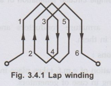
•As
seen from the Fig. 3.4.1, there is overlapping of coils while proceeding.
Key Point:
Due to such connection, the total number of conductors get divided into 'P'
number of parallel paths, where P = Number of poles in the machine.
•
Large number of parallel paths indicate high current capacity of machine hence lap
winding is preferred for high current rating generators.
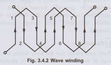
2. Wave Winding
•
In this type of connection, winding always travels ahead avoiding overlapping.
It travels like a progressive wave hence called wave winding. To get an idea of
wave winding a part of armature winding in wave fashion is shown in the Fig.
3.4.2.
•
Both coils starting from slot 1 and slot 2 are br progressing in wave fashion.
Key Point:
Due to this type of connection, the total number of conductors get divided into
two number of parallel paths always, irrespective of number of poles of the
machine. As number of parallel paths are less, it is preferable for low
current, high voltage capacity generators.
•
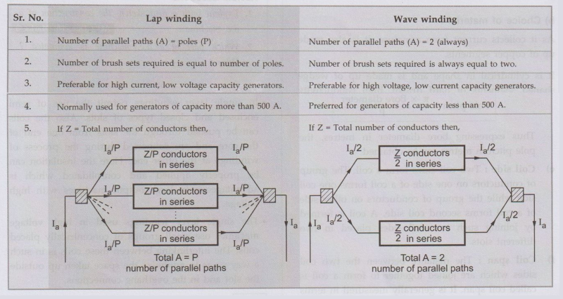
The number of parallel paths in which armature conductors are divided due to
lap or wave fashion of connection is denoted as A. So A = P for lap connection
and A = 2 for wave connection.
3. Comparison of Lap and Wave Type Windings
4. Winding
Terminologies
a) Conductor:
It is the actual armature conductor which is under the influence of the
magnetic field, placed in the armature slot.
b) Turn:
The two conductors placed in different slots when connected together, forms a
turn. While describing armature winding the number of turns may be specified
from which, the number of conductors can be decided.
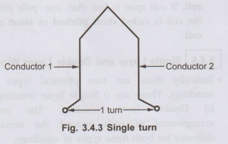
Z
= 2 × Number of turns
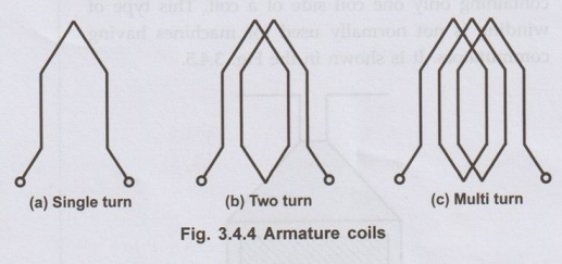
c) Coil:
For simplicity of connections, the turns are grouped together to form a coil.
If
coil contains only one turn it is called single turn coil while coil with more
than one turn is called multiturn coil.
Hence
if number of coils, alongwith number of turns per coil are specified, it is
possible to determine the total number of turns and hence total number of
armature conductors 'Z' required to calculate generated e.m.f.
d) Pole-pitch:
The distance between the two adjacent poles is called a pole pitch. It is
measured interms of number of slots. Thus total slots along the periphery of
armature divided by the total number of poles is called a pole pitch.
Pole pitch = Number of armature slots
/ P
If
armature bore diameter is given then the pole pitch can be obtained as,
Pole
pitch = π × Вore diameter / P
Thus
expressing bore diameter in metres, the pole pitch in metres can be obtained.
e) Coil side:
Two coil sides form a coil. The group of conductors on one side of a coil forms
one coil side while the group of conductors on other side of a coil forms
second coil side. A coil is formed by joining such two coil sides placed in two
different slots.
f) Coil span:
The distance between the two coil sides which are joined together to form a
coil is called coil span. It is generally measured in terms of number of slots.
If the coil span is equal to one pole pitch then the coil is called full pitch
coil. If coil span is less than one pole pitch then the coil is called short
pitched or short chorded coil.
5. Single Layer and Double Layer Winding
•
Basically there are two physical types of the windings. These are i) Single
layer winding ii) Double layer winding. The sequential arrangement of coils
around the armature is different for both these types of windings.
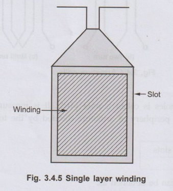
a. Single Layer Winding
•
In this type of winding, the complete slot is containing only one coil side of
a coil. This type of winding is not normally used for machines having
commutators. It is shown in the Fig. 3.4.5.
•
In single layer windings permit the use of semi enclosed and closed types of
slots. Also the coils can be pushed through the slots from one end of the core
and are connected during the process of windings at the other end. Here the
insulation can be properly applied and consolidated which is advantageous in
large output machines with high voltage.
•
The single layer windings used in high voltage machines use small groups of
concentrically placed coils. The interlinking between these coils is in such a
way so as to minimize the space taken up outside the slot and in the overhang
connections.
b. Double Layer Winding
•
It is shown in the Fig. 3.4.6. It consists of identical coils with one coilside
of each coil in top half of the slot and the other coilside in bottom half of
another slot which is nearly one pole pitch away.
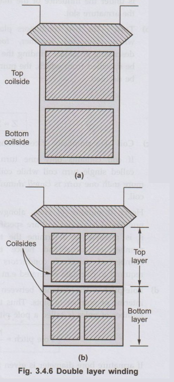
•
In the Fig. 3.4.6 (a) there are two coilsides per slot while in Fig. 3.4.6 (b)
there are eight coilsides per slot. Each layer may contain more than one coil
side if large number of coils are required. For placing double layer windings,
usually open slots are used.
Advantages of Double Layer Winding
The
double layer winding has following advantages,
1.
It provides neat arrangement as all coils are identical.
2.
Greater flexibility can be achieved with double layer winding as coil span can
be easily selected.
6. Closed and Open Windings
•
Armature windings are classifed into two different types namely i) Closed type
winding ii) Open type winding.
a. Closed Type Winding
•
In this type of winding, a closed path is formed around the armature. The
starting point of the winding is reached again after passing through all the
turns. The current passing through closed type winding is through brushes
placed on commutator. The commutator segments are connected to various armature
coils.
.•
The armature current gets divided into different parallel paths. The current
flowing through the coil changes continuously but from brush side the winding
view remains same and polarity is maintained which is in effect due to use of
commutator segments.
•
The closed type of winding is normally used in a.c. and d.c. commutator
machines. This type of winding is usually double layer.
b. Open Type Winding
•
In case of a.c. machines, commutator is not used and hence closed winding is
not required to be used. In such cases open type winding is used. The armature
is left open at one or more points.
.
•
The ends of each section of the winding can be brought at the terminals to do
the required type of interconnection externally. The open type of winding is
preferred over closed type as it gives better flexibility in design and freedom
of connections.
•
These type of windings are either single layer type or double layer type and
are mainly used in induction machines and synchronous machines.
Review Questions
1. What are the
ordinary types of armature winding for d.c. machine? Explain the essential difference
between them and give relative merits and the applications of the two types
windings.
2. Distinguish
between lap and wave windings.
3. Define the
following terminology of armature winding of a d.c. machine: i) Conductor ii)
Turn iii) Coil and coil side iv) Coil span.
Electrical Machines: Unit II: D.C. Generators : Tag: : DC Generators - Types of Armature Winding
Related Topics
Related Subjects

Electrical Machines I
EE3303 EM 1 3rd Semester EEE Dept | 2021 Regulation | 3rd Semester EEE Dept 2021 Regulation