Electrical Machines II: UNIT I: a. Synchronous Generator
Types of Armature Windings
Synchronous Generator
In general armature winding is classified as, i) Single layer and double layer winding ii) Full pitch and short pitch winding iii) Concentrated and distributed winding.
Types of Armature Windings
In
general armature winding is classified as,
i)
Single layer and double layer winding
ii)
Full pitch and short pitch winding
iii)
Concentrated and distributed winding.
Let
us see the details of each classification.
1. Single Layer and Double Layer Winding
If
a slot consists of only one coil side, winding is said to be single layer. This
is shown in the Fig. 1.11.1 (a).

While
there are two coil sides per slot, one at the bottom and one at the top the
winding is called double layer as shown in the Fig. 1.11.1 (b).

A
lot of space gets wasted in single layer hence in practice generally double
layer winding is preferred.
2. Full Pitch and Short Pitch Winding
As
seen earlier, one pole pitch is 180° electrical. The value of 'n', slots per
pole indicates how many slots are contributing 180° electrical phase
difference. So if coil side in one slot is connected to a coil side in another
slot which is one pole pitch distance away from first slot, the winding is said
to be full pitch winding and coil is called full pitch coil.
For
example in 2 pole, 18 slots alternator, the pole pitch is n = 18/2 = 9 slots. So if coil side in slot No. 1
is connected to coil side in slot No. 10 such that two slots No. 1 and No. 10
are one pole pitch or n slots or 180° electrical apart, the coil is called full
pitch coil.
Here
we can define one more term related to a coil called coil span.
a.
Coil Span
It
is the distance on the periphery of the armature between two coil sides of a
coil. It is usually expressed in terms of number of slots or degrees
electrical. So if coil span is 'n' slots or 180° electrical the coil is called
full pitch coil. This is shown in the Fig. 1.11.2.

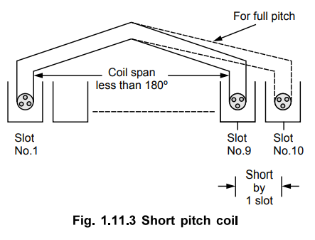
As
against this if coils are used in such a way that coil span is slightly less
than a pole pitch i.e. less than 180° electrical, the coils are called, short
pitched coils or fractional pitched coils. Generally coils are shorted by one
or two slots.
So
in 18 slots, 2 pole alternator instead of connecting a coil side in slot No.l
to slot No.10, it is connected to a coil side in slot No.9 or slot No. 8, coil
is said to be short pitched coil and winding is called short pitch winding. This
is shown in Fig. 1.11.3.
b.
Advantages of Short Pitch Coils
In
actual practice, short pitch coils are used as it has following advantages :
a)
The length required for the end connections of coils is less i.e. inactive
length of winding is less. So less copper is required. Hence economical.
b)
Short pitching eliminates high frequency harmonics which distort the sinusoidal
nature of e.m.f. Hence waveform of an induced e.m.f. is more sinusoidal due to
short pitching.
c)
As high frequency harmonics get eliminated, eddy current and hysteresis losses
which depend on frequency also get minimised. This increases the efficiency.
3. Concentrated and Distributed Winding
In
three phase alternators, we have seen that there are three different sets of
windings, each for a phase. So depending upon the total number of slots and
number of poles, we have certain slots per phase available under each pole.
This is denoted as'm'.
m
= Slots per pole per phase = n/number of phases
=
n/3 (generally number of phases is 3)
For
example in 18 slots, 2 pole alternator we have
n
= 18/2 = 9
and
m = 9/3 = 3
So
we have 3 slots per pole per phase available. Now let 'x' number of conductors
per phase are to be placed under one pole. And we have 3 slots per pole per
phase available. But if all 'x' conductors per phase are placed in one slot
keeping remaining 2 slots per pole per phase empty then the winding is called concentrated
winding.
Key Point : So in
concentrated winding all conductors or coils belonging to a phase are placed in
one slot under every pole.
But
in practice, an attempt is always made to use all the'm' slots per pole per
phase available for distribution of the winding. So if 'x' conductors per phase
are distributed amongst the 3 slots per phase available under every pole, the
winding is called distributed winding. So in distributed type of winding all
the coils belonging to a phase are well distributed over the 'm' slots per
phase, under every pole. Distributed winding makes the waveform of the induced
e.m.f. more sinusoidal in nature. Also in concentrated winding due to large
number of conductors per slot, heat dissipation is poor.
Key Point : So in practice,
double layer, short pitched and distributed type of armature winding is
preferred for the alternators.
Review Question
1. Discuss the comparison between the following in an alternator
:
i) Single layer and double layer windings
ii) Full-pitch and short pitch coils
iii) Concentrated and distributed winding.
Electrical Machines II: UNIT I: a. Synchronous Generator : Tag: Engineering Electrical Machines - II : Synchronous Generator - Types of Armature Windings
Related Topics
Related Subjects

Electrical Machines II
EE3405 Machine 2 EM 2 4th Semester EEE Dept | 2021 Regulation | 4th Semester EEE Dept 2021 Regulation