Basic Civil & Mechanical Engineering: UNIT III: k. Dams
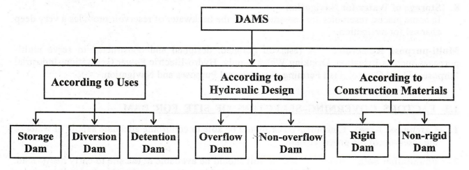
Types of dams
Civil Engineering
A Storage Dam is constructed for storing the surplus water available in the river during the rainy season. Otherwise, the excess water from the river flows into the sea. The water thus stored is used for irrigation during dry months.
TYPES OF DAMS
See
the Chart given below:
•
Storage Dams
A
Storage Dam is constructed for storing the surplus water available in the river
during the rainy season. Otherwise, the excess water from the river flows into
the sea. The water thus stored is used for irrigation during dry months.
Examples:
Gravity Dam, Earth Dam, Arch Dam and Rock Fill Dam.
•
Diversion Dams
A
Diversion Dam is built across a river to raise the water level which can be
diverted into canals to the place of use.
Examples:
Weir Dam and Barrage Dam.
•
Overflow Dams
Overflow
Dam is constructed to carry surplus discharge of water, including flood water,
over its crest.
Examples:
Spillways.
•
Non-overflow Dams
In
a Non-overflow Dam, the top surface of the dam (crest) is kept at a higher
level than the maximum expected High Flood Level.
Examples:
Gravity Dam, Earth Dam and Rock Fill Dam.
•
Rigid Dams
As
the name implies, a Rigid Dam is constructed using rigid construction materials
such as Stone Masonry, R.C.C. or P.C.C., Steel and Timber. Basic profile of a
rigid dam is a triangle.
Examples:
Solid
Masonry or Concrete Gravity Dam, Arched Masonry or Concrete Dam, Buttress Dam,
Steel Dam and Timber Dam.
•
Non-rigid Dams
A
Non-rigid Dam is constructed of non-rigid materials such as Earth Soil or
Rock-fill. It has a trapezoidal basic profile. These dams are flexible
structures. They can deform slightly corresponding to the deflection of the
foundation.
Examples:
Earth Dam and Rock Fill Dam.
1. GRAVITY DAM
A
Gravity Dam is a rigid-type of dam. It is constructed of concrete or masonry
Masonry Gravity Dams are constructed only in small heights. But, all major
important gravity dams are now-a-days constructed of concrete only.
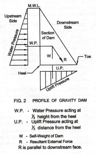
1.
Profile of Gravity Dam
See
Fig. 2. The cross-section of the gravity dam is a right-angled triangle in
elevation with upstream water on the vertical side. However, the triangular
profile cannot be adopted in practice.
A
modified profile in trapezoidal shape (Fig. 3) is designed with (i) Free Board
and Roadway at the top and (ii) Lower Supply Sluice. The size of the cross
section of the dam is designed such that its self-weight resists all the
disturbing external forces acting on it. External forces acting on the gravity
dam are as follows:
1.
Water Pressure (W.P.)
Water
stored in the upstream side exerts a pressure on the dam. The intensity of
pressure varies in a triangular fashion. The intensity of water pressure at the
Maximum Water Level (M.W.L.) is nil. Water pressure is maximum at the Heel.
2.
Uplift Pressure (U.P.)
The
upstream side and downstream side of the dam has a difference in Water Head.
This water head causes seepage of water through the pores (porous concrete) of
the dam and its foundation.
The
seeping water causes an upward pressure, called Uplift Pressure on the dam.
Uplift causes instability to the dam. Intensity of uplift pressure varies in a
triangular fashion. It is nil at the toe. It is maximum at the heel.
3.
Pressure due to Earthquake Forces: Earthquake Forces may
set up waves in the crust of the earth. These waves develop high stresses,
causing instability to the dam.
4.
Wind Pressure: It acts on the exposed area of the dam.
It is rather a minor force.
5.
Self-Weight of the Dam (W)
Self-Weight
of the Dam is the main resisting force of the dam. It is designed such that it
is able to resist the total disturbing external forces acting on it. Thus, the
forces disturbing the stability of the dam are resisted by the gravity force of
the mass of the dam and hence the name Gravity Dam. Therefore, the gravity dam
needs a Hard Foundation Rock.
Resultant
Force R is made parallel to the hypotenuse of the triangle. Thus, the basic
profile of the dam is a triangle.
2.
Components of Gravity Dam (Fig. 3)
It
consists of: Reservoir, Upstream Face, Downstream Face, Crest, M.W.L., Free
Board, Upper Supply Sluice, Lower Supply Sluice, Heel, Toe, Drainage Gallery
and Hard Foundation Rock (Impervious Strata).
1.
Upper Supply and Lower Supply Sluices:
Supply
Sluices, namely, Upper Supply and Lower Lower Supply Sluice are openings
provided through the body of the dam from its Upstream side to the Downstream
side. The sluices with necessary shutters release the required quantity of
water from the reservoir.
2.
Spillway:
During
floods, the quantity of incoming water will be heavy. The surplus water beyond
the storage capacity of the reservoir has to be immediately diverted safely. A
Spillway is the overflow portion of the dam, over which surplus discharge flows
from the reservoir to the downstream.
3.
Drainage Gallery: It is an opening provided in the dam,
few meters away from the upstream vertical face. It may be in longitudinal or
transverse direction. Drainage Gallery collects the seeping water and
discharges it through the Cross Gallery (as shown). Thus, it relieves the
uplift pressure in the dam. Hence, the stability of the dam is protected. Also,
drainage gallery serves as a Longitudinal Inspection Chamber.
3.
Advantages
1.
Use:
Gravity dam is most suited at sites with narrow gorges or valleys and steep
side slopes. It is adopted for use as an Overflow Dam.
2.
Maximum Rigidity: Gravity dam has maximum rigidity, due
to its heavy and solid self weight. Hence, it is also named as Solid Gravity
Dam.
3.
Durability: It is highly durable with less
maintenance.
4.
Height of the Dam: It can be constructed of any height,
provided suitable foundation is available to withstand the loads on it.
5.
Stability: It is relatively stronger and more stable than
Earth Dam.
6.
No Sudden Failure: Failure of the gravity dam, if any, may
not suddenly occur.
4.
Disadvantages
1.
Rock Foundation: Gravity dam can be constructed only on
sound rock foundation.
2.
Causes of Failure: A gravity dam may fail due to
overturning or sliding or crushing, due to the heavy self-weight of the dam and
forces acting on it.
3.
Rising the Height: Unless specific provision is made in
the initial design itself, it will be very difficult to rise the height of the
dam subsequently.
4.
Initial Cost: Initial cost is higher than the Earth
Dam.
5.
Skilled Labour: Skilled labour is required for its
construction.
2. ARCH DAM
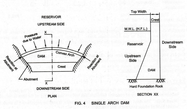
See
Fig. 4. Arch Dam is a rigid-type dam, curved in plan as shown. It has a
constant horizontal radius on the upstream side. Its Convex Face is facing the
reservoir (upstream) side. Strong Abutments are constructed on either side of
the dam.
Stability
The
arch dam depends on the arch action for its stability. The water
pressure on the upstream side is transferred horizontally to the Abutments on
either side of the dam by arch action. The forces involved are: Water Pressure
and a slight Uplift Pressure, which may lead for the yielding of abutment.
Therefore, the abutments should be very strong to withstand these forces.
Advantages
1.
The arch dam is suitable for narrow valleys or gorges.
2.
Arch dam requires less construction materials and is hence less massive. Saving
in the quantity of concrete is around 50% compared to gravity dam. This is
because of its better structural effectiveness.
3.
When the height of the dam is more than its length, an arch dam is economical. Therefore,
this dam is preferable for very great heights.
3. R.C.C. BUTTRESS DAM
R.C.C.
Buttress Dam is constructed
(i)
where the river is wide,
(ii)
where the foundation soil is pervious and
(iii) where the height of the dam required is
less.
See
Fig. 5. A buttress dam consists of a series of R.C.C. Buttresses, Foundation
Slab or Base Slab, a sloping R.C.C. Face Slab or Deck Slab, lateral beams called
Braces and Cut-off Wall.
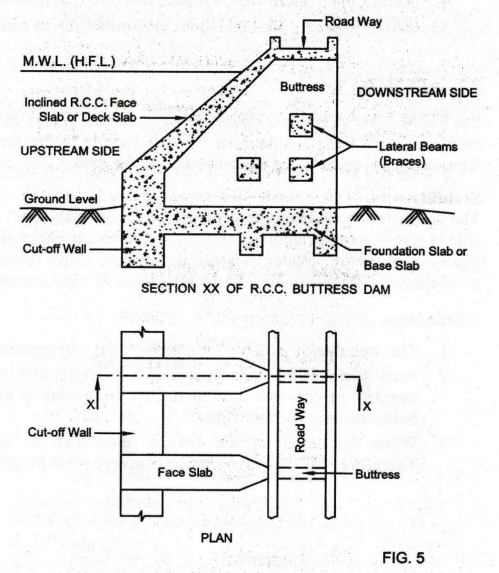
A
buttress dam has a continuous Upstream Face, inclined at about 45° to the
horizontal. It is supported at regular intervals by a series of Downstream
Buttresses or Piers.
The buttresses divide the space of the dam into a number of spans. Panels of Flat Slabs or Deck Slabs are constructed between the buttresses.
Sloping
R.C.C. Face Slab takes the water load from the upstream side. The flat slab
transfers the water load to the buttresses which are at regular intervals.
Buttresses, in turn, transfer the water load to the Foundation Slab. Lateral
Beams called Braces are provided between the series of buttresses along the
entire length of the dam.
Cut-off
Wall
Cut-off
wall is constructed below the Ground Level. Due to the difference in Water Head
between the upstream and downstream sides, the water may seep through the
foundation and body of the dam. The seeping water exerts an uplift pressure on
the dam. Cut-off wall reduces the uplift pressure on the foundation.
1.
Advantages
1.
Stability: Weight of water on the inclined face
slab helps to the stability of the dam. So, the requirement of quantity of
concrete becomes less and the dead weight of the dam is reduced.
2.
Weak Soil: The dead weight of the dam is less.
Hence, it may be constructed in weak soil, where hard or rocky stratum is not
available.
3.
Height of the Dam: Height of the buttress dam can be
easily increased by simply extending the buttresses and the face slabs.
4.
Lateral Beams (Braces): The braces add to the strength of
the buttresses.
5.
Space between Buttresses: The space available
between the buttresses is very large. It may be used for housing
water-treatment plants and power houses.
6.
Economical: In the gravity dam, full strength of
concrete is not utilized at all the points. This is uneconomical. But, in a
buttress dam, total volume of concrete is reduced by concentrating the
materials where stresses are more. Thus, the buttress dam has relatively thin
Face Slab section.
4. STEEL DAM
Steel
Dams are constructed only in small sizes for low capacity reservoirs. However,
it requires periodical painting. These are not in use now-a-days. The steel dam
consists of a steel frame work with a thick steel plate called Flat Slab.
5. TIMBER DAM
A
Timber Dam is constructed only in small size for low capacity reservoirs.
However, it is also used only for temporary purposes such as to divert the flow
of river water for the construction of a main dam. After the construction of
the main dam, the timber dam will be dismantled. The height of the timber dam
is restricted to 9 meters only. Timber dam cannot be made water-tight.
6. EARTH DAMS
Earth
Dam is a non-rigid type of dam with a trapezoidal profile. It is made of
locally available soils and gravels with minimum processing. This makes the
cost of construction cheaper than a rigid dam. Therefore, it is the most common
type of dams, constructed in the areas where the foundation is not sufficiently
strong enough to bear the weight of a gravity dam. Earth dams can be
constructed for moderate heights.
An
embankment with a core arrangement to prevent water seepage is an Embankment
Dam.
Types
of Earth Dam
Based
on the construction materials used, earth dams are classified as:
1.
Homogeneous Embankment Earth Dam
2.
Zoned Embankment Type Earth Dam
3.
Diaphragm Type Embankment Earth Dam
1.
Homogeneous Embankment Earth Dam
See
Fig. 6. It is the simplest type of earth dam of trapezoidal profile. It
consists of a single kind of Earth material (excluding the material used for
Slope Protection). It is homogeneous throughout the structure and hence the
name Homogeneous Earth Dam.
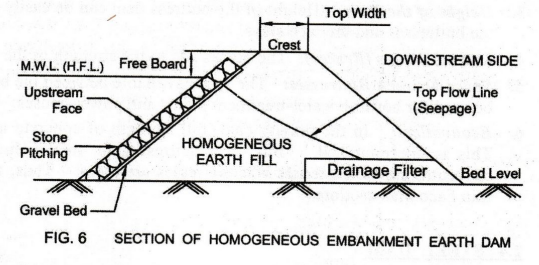
Use:
Homogeneous embankment earth dam is structurally not strong. It is not
frequently used. Homogeneous embankment earth dams are of 6 to 8 meters height.
Many of the existing low to moderate height dams are of this type.
Stability
A purely homogeneous type of non rigid construction results in seepage of water will affect the stability of the dam.
A
Drainage Filter is provided to check the seepage of water through the dam.
Also,
stones are pitched (called Stone Pitching) on the Gravel Bed, over the inclined
Upstream Face of the dam. This is known as Slope Protection arrangement. It
protects the dam from seepage of water and wave action causing erosion. Thus,
the stability of the dam is improved.
2.
Zoned Embankment Type Earth Dam
See
Fig. 7. This type of dam consists of two zones, viz., Inner Zone and Outer
Zone, and hence the name Zoned Type. Inner Zone is made of impervious soil.
Therefore, inner zone is called Inner Impervious Core, formed along the length
of the dam. Outer Zone is made of pervious soil. Hence, outer zone is called
Outer Pervious Shell or Casing. The inner core is supported and protected by
the outer shell.
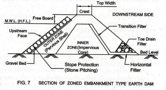
The
dam is composed of more than one material. The materials for inner core are
clay, clayey soil, silt or mixture clay and silt. The materials for outer shell
are locally available soils such as sands, gravels, cobbles, rocker pieces or
combination of these materials.
The
Crest is about 5 meters wide (Top Width) with a paved road to enable access for
inspection and maintenance.
Use
Zoned
embankment dam can be used for dams of moderate or great heights.
Stability
The
inner impervious core zone gives added strength to the structure of the dam. It
reduces the percolation of water through the dam.
Seepage
within the dam section is controlled using drains. Drainage systems in the form
of inclined Transition Filter, Horizontal Filter and Toe Filter are provided.
These filters collect the seeping water and drain the same to the downstream
side of the dam. Thus, this arrangement ensures the stability of the dam.
The
Upstream Face is protected against erosion due to wave action. For this, Stone
Pitching or Slope Protection or Revetment is provided.
3.
Diaphragm Type Embankment Earth Dam
See
Fig. 8. This dam consists of a thin impervious wall of masonry, cement
concrete, impervious. soils, steel or timber, known as Core. Core is
constructed in the middle of the section along the length of the dam. This core
is called Diaphragm.
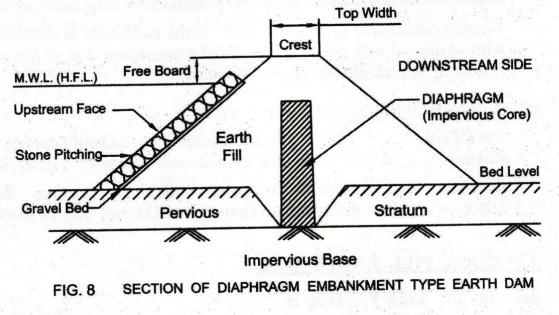
The
diaphragm is surrounded by earth fill. It is joined to a strong impervious
foundation bed. The diaphragm core arrests leakage or seepage of water to a
great extent. The upstream face of the dam is protected by Stone Pitching or
Stone Revetment. Stone pitching is laid on a Gravel Bed.
1.
Advantages of Embankment Earth Dams
1.
Uses: Embankment earth dams are suited to wide variety of
foundation conditions. They are suitable to both steep gorges (narrow valleys)
and wide valleys.
2.
Local materials can be made use of.
3.
Reduced cost of construction.
4.
About 80% of the total number of dams in the World are earth dams.
2.
Failures of Earth Dams
Failures
of earth dams are of three types:
1.
Seepage Failures
Poor
bond between embankment and foundation and also poor compaction of soil cause
leakage. Concentrated leakage results in erosion. See Fig. 9.
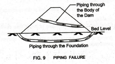
Piping
Failure: Progressive erosion of soil will result in Piping.
Thus, unsafe seepage slope causes piping failure. Piping occurs through the
foundation or the body of the dam.
2.
Structural Failures
Improper
Design and Construction – High Steepness: If the earth
dam is constructed with high steepness of side slopes, shear slips will occur.
The slopes are protected by stone revetment over a layer of gravel bed. In the
event of heavy storm, the stone revetment may be washed out of the layer by the
forces generated by the storm waves.
Slipping
of Land: Slipping of upstream slope and
downstream face may occur.
Improper
Maintenance: Improper maintenance may cause
structural failures.
Uneven
Settlement of Foundation: If the earth dam is
constructed above stratified deposits with layers of soft clay, it may fail by
spreading due to the consolidation of clay. This results in uneven settlement
of the foundation.
3.
Hydraulic Failures
Over
Topping: Hydraulic failure occurs due to Over
Topping. Over Topping is the overflowing of water in the dam due to inadequate
capacity spillways and insufficient free board.
Erosion:
Hydraulic failure may also occur due to Erosion. Erosion is caused by the wave
action of water on the upstream slope. Erosion may also be due to rain on
downstream slope.
7. ROCK FILL EARTH DAM
See
Fig. 10. Rock Fill Dam is made up of various sizes of loose Rocks (hence the
name Rock Fill Dam) and boulders at the downstream side to provide stability.
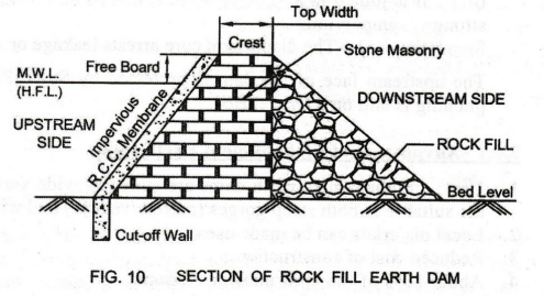
The
dam is made of dry rubble Stone Masonry on the upstream side. Impervious R.C.C.
Membrane (covering) is laid on the sloping side of the stone masonry for water AM
tightness.
Cut-off
Wall is provided at the upstream side to check the seepage in the foundation
soil.
Stability
Stability
of the rock fill dam is better than earth dam. The rock fill dam is flexible in
nature. Hence, it has very good resistance against earthquake forces. However,
it is less stable than gravity dam. It may also be subjected to uneven
settlement failure, causing cracks in the R.C.C. membrane.
Basic Civil & Mechanical Engineering: UNIT III: k. Dams : Tag: : Civil Engineering - Types of dams
Related Topics
Related Subjects

Basic Civil and Mechanical Engineering
BE3255 2nd Semester 2021 Regulation | 2nd Semester EEE Dept 2021 Regulation