Transmission and Distribution: Unit III: (b) Insulators
Types of Insulators
Pin T- Suspension - Strain - Shackle - Stay
The use of proper insulator is an important part of the mechanical design of the overload lines. The various types of the insulators are, 1. Pin type insulators 2. Suspension type insulators 3. Strain insulators 4. Shackle insulators 5. Stay insulators
Types of Insulators
The use of proper insulator is an
important part of the mechanical design of the overload lines. The various
types of the insulators are,
1. Pin type insulators
2. Suspension type insulators
3. Strain insulators
4. Shackle insulators
5. Stay insulators
1. Pin Type Insulators
A typical pin type insulator is shown in
the Fig. 5.3.1.
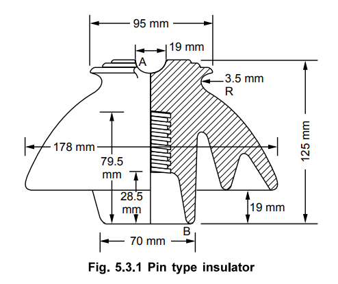
For lower voltages upto 11 kV generally
one piece pin type insulator is used.
But for higher working voltages like 33
kV, 45 kV, 66 kV and beyond it two piece, three piece, four piece pin type
insulators can be used. But its use is restricted upto 33 kV as for higher
voltages, the pin insulators are uneconomical. The pin insulators become very
bulky for higher voltages.
On the upper end, there is a groove for
housing the conductor. The pin insulators are very firmly secured to the cross
arm on the transmission pole with the help of steel bolts. To avoid the direct
contact of hard metal with porcelain, the lead screws are used. In such case
two methods are used to secure insulator to the bolt.
1. The porcelain insulator has cement
threads which are lined with a soft material like lead. The pin is screwed into
such cement screw.
2. Solid lead screw is casted on the
head of the pin and is screwed directly into the porcelain.
Such type of insulators are used for the
transmission lines which are running straight.
The conductor passes through the groove
on the upper end and is bound by the binding wire of soft copper or soft
aluminium i.e. of the same material as that of conductor. This is shown in the
Fig. 5.3.2. The binding wire should cover at least 4 to 5 turns before its ends
are wrapped with the conductor.
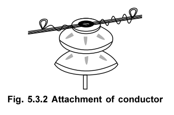
When the insulators are wet their outer
surface is Fig' 5'3'2 Attachment of conductor almost conducting. To keep the
inner side of the insulator dry, the rain sheds are provided or now a days
surfaces are provided with petticoats. But design of these sheds or petticoats
is such that their surface must lie along the equipotential surfaces of the
electrostatic fields while the body is so shaped to lie along the lines of the
electrostatic fields. Due to this, leakage resistance of each shell remains
almost same, keeping capacitance of each
shell also same. Due to this, there is uniform voltage distribution along the
shells. Such petticoats help to avoid flashover and leakage current also.
2. Suspension Type Insulators
As the voltage level increases, pin type
insulators become very bulky and their cost also increases rapidly. Hence the
most popular insulators used for very high voltage transmission lines are
suspension type insulators. These insulators have number of porcelain disc
units. These units are connected to one another in series with the help of
metal links. This forms a string of porcelain discs. The top most insulator
unit is connected to the cross arm of the tower while the lowest insulator is
made to hold the conductor along the conductor shoe. Each unit is designed for
the low voltage for say 11 kV but a string of such units give us the proper
insulation against very high voltage levels.
The two important types of suspension
type insulators are,
1. Cemented cap type
2. Hewlett or inter-linking type
The cemented cap type is the most
commonly used suspension type insulator. The Fig. 5.3.3 shows the cemented cap
type suspension insulator.
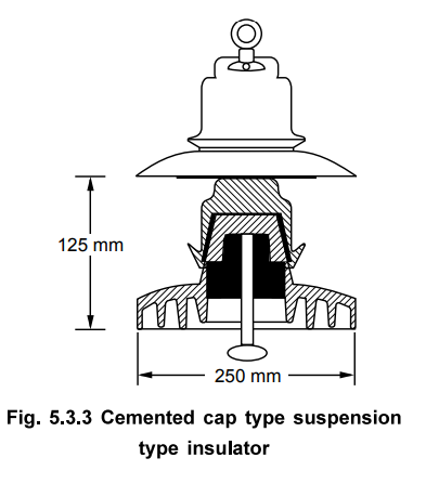
It consists of a single disc shaped
piece of porcelain. At the bottom, it is grooved so as to increase the flash
over distance. A galvanised cast iron cap is cemented at the top. The space is
provided in the cap, which can be used to hold the pin of another unit. The cap
is cemented to the insulator. And the pin is either cemented or connected by
means of steel wire spring ring. The main drawback of this type is that the
cubical expansions of three materials iron, porcelain and cement are different
from each other and due to this fine cracks in the insulator and early failure
is possible.
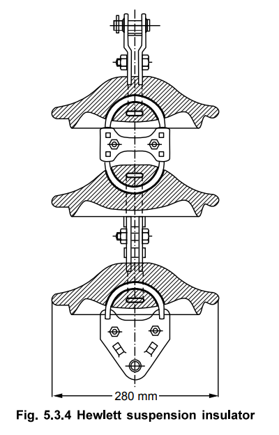
The Hewlett type insulator is more
simple in design. It consists of a porcelain disc. The top portion of the disc
consists of two curved tunnels, the planes of which are at right angles to each
other. Lead covered steel U links are passed through the tunnels. These links
are bolted to the two similar units at the top and bottom. No cementing is
required in this type of insulator. The mechanical strength of this type is
also very high due to the use of steel links. Another advantage of this type is
that even if porcelain breaks due to the
links, the units are held togther and there is no interruption in the working.
But the main disadvantage of this type is that the porcelain in between is
under high electrostatic stress and hence there is possibility of puncture
earlier than the cemented cap type. Hence cemented cap type is more preferred
than Hewlett type. The Hewlett type insulator is shown in the Fig. 5.3.4 .
The overall string of suspension type
insulators is shown in the Fig. 5.3.5.
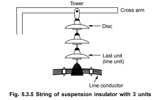
The top unit is fastened to the cross
arm of the tower. The lowest unit holds the line conductor. This bottom most
unit, which is nearest to the line conductor is also called line unit.
a. Advantages of Suspension Type
Insulators
The various advantages of the suspension
type insulators are,
1. For higher voltages, these are
cheaper than the pin insulator.
2. Each unit is designed for low voltage
level such as 11 kV but by connecting such units in series to form a string,
insulator for any higher voltage level can be designed.
3. In case of failure of any of the
units, the replacement work can be done very easily and entire string need not
be replaced.
4. If the line voltage is required to be
increased at some later stage to satisfy increased load demand then just by
adding additional units to the string, same insulator can be used. Adding such
units is very easy.
5. This type of insulator provides
greater flexibility to the line. The string is suspended and is free to swing
in any direction. So it takes the position so that mechanical stresses on the
line are minimum.
6. When used with the steel towers, the
line conductors are less affected by lightning. This is because the conductor
is lower than the earthed cross arm and the arrangement acts as a lightning
arrester.
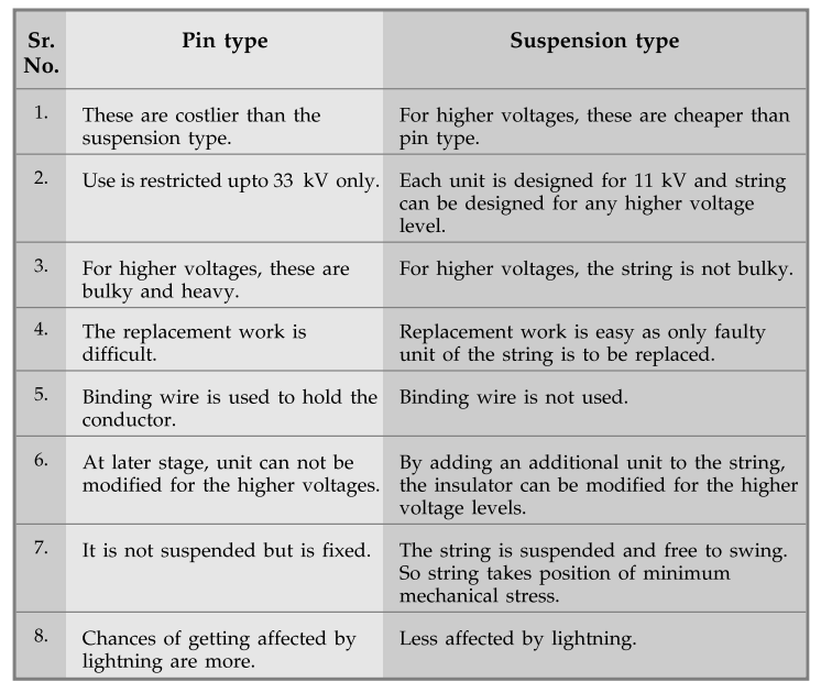
b. Comparison of Pin and Suspension Type
The comparison is given in the following
table,
3. Strain Insulators
These insulators are used when there is
dead end of the line or corner or line is at a sharp curve or the line is
crossing the river etc. These insulators reduce the excessive tension on the
line under such abnormal conditions. For low voltage lines below 11 kV shackle
insulators are used but for higher voltages strain insulators are used.
Assembly of the suspension insulators is used as a strain insulator. The discs
of the strain insulators are in a vertical plane instead of the horizontal
plane as in the suspension insulators. In case of conditions like crossing of
the river, there is excessive tension on the line. In such a case, two or more
strings of the insulators are used in parallel.
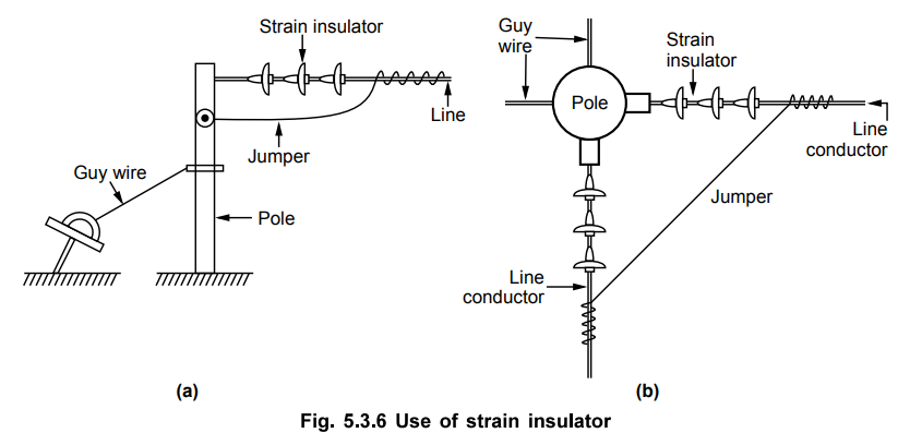
The Fig. 5.3.6 (a) shows the use of
strain insulator. The Fig. 5.3.6 (b) shows the plan of the line.
4. Shackle Insulator
These are also called spool insulators.
These are primarily used for low voltage distribution lines. These insulators
can be used in horizontal position or in vertical position. These are used at
the dead end of the aerial wire of service connection to a house or a factory
where there is excessive mechanical stress on the line.
The Fig. 5.3.7 shows the shackle type
insulator.
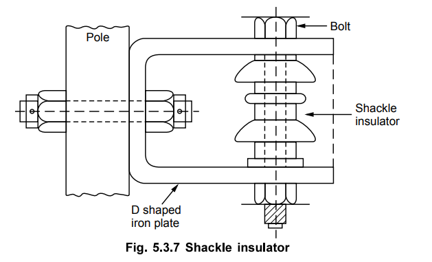
The insulator is round. It has through
hole in the centre for the bolting purpose. On each side of the insulator,
there is galvanised iron plate of 25 mm wide. The other end of plates are
placed around the cross arm of the channel or pole. The conductor is in the
groove and it is secured with the help of soft binding wires. Similar to the
strain insulators, these insulators are effective when there is dead end of the
distribution line or the distribution line changes its angle.
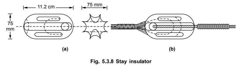
5. Stay Insulators
The stay insulators are also called egg
insulators. In case of low voltage lines, it is necessary that the stays are to
be insulated at a height of not less than 3 meters from ground. The stay
insulators are used on stay wire to create insulation between pole and stay
clamp. It is usually made of porcelain. It has two holes for the stay wires and
the design is such that in case the insulator breaks then the stay wire will
not fall on the ground.
The Fig. 5.3.8 shows the stay insulator
and the method of inserting the stay wires into the stay insulator.
Review Questions
1. Write a note on different types of overhead insulators.
2. Give the list of various insulators and compare pin and
suspension type insulators.
3. Draw and explain the construction of Hewlett type suspension
type insulator.
4. With the help of neat figure, explain pin type insulator.
5. Draw with neat sketches and explanation of pin and suspension type insulators. Compare their merits and demerits.
Transmission and Distribution: Unit III: (b) Insulators : Tag: : Pin T- Suspension - Strain - Shackle - Stay - Types of Insulators
Related Topics
Related Subjects

Transmission and Distribution
EE3401 TD 4th Semester EEE Dept | 2021 Regulation | 4th Semester EEE Dept 2021 Regulation